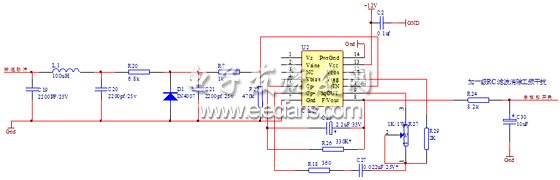
1 Introduction There are many types of bus technology. In terms of cost, the cost of RS-232 / 485 is lower than CAN; in terms of speed, industrial Ethernet, etc. are also good. Why is CAN alone the favorite in automotive electronics? In terms of cost, CAN is higher than UART and RS-232 / 485, but lower than Ethernet; in terms of real-time: CAN's real-time is higher than UART and Ethernet. In order to ensure safety, vehicle communication protocols are based on Actively send periodically, whether it is CAN or LIN, the transmission cycle of messages with high real-time requirements is less than 10ms (each car has several such messages), and the engine, ABS and transmission have several such messages; In terms of reliability, CAN has a series of accident safety measures, which are not available in UART and Ethernet. Multi-point redundancy is also difficult to achieve with UART (point-to-point transmission) and industrial Ethernet (short data transmission distance), so CAN After the emergence, due to price reasons, the initial application is not the car, but the cost-insensitive industrial control and medical equipment, such as: industrial DEVICENET, SDS, CANOPEN, medical MRI, etc. As for the emergence of industrial Ethernet, its background is inseparable from the popularity of personal PCs. Now PCBASED in industrial control is an example, but car control cannot use a PC. To meet the requirements of car control, the cost Not allowed. The transmission process of LIN is only 20Kbps, which obviously cannot be used as an independent automotive bus control requirement. Generally, it only cooperates with CAN for auxiliary use in automobiles. Vehicles are a special application environment. The continuous improvement of vehicle automation has put forward higher requirements for vehicle instruments. Traditional dynamic magnetic instruments have become increasingly unsuitable for the development of modern intelligent vehicles. The features of interaction, intelligence, and ease of expansion are widely valued. This topic requires the design of a set of virtual instruments for a car. The host computer uses a PC104 embedded microcomputer based on the RTOS development environment. As one of the most important subsystems of virtual instrumentation, the vehicle environmental data collection system requires the completion of data collection and communication functions, and it has high timeliness and reliability. Based on the author's experience, this article introduces the method of designing vehicle data acquisition system with Philips' high-performance single-chip P80C592, and focuses on the system design and CAN communication programming. 2 System Introduction According to the design requirements, this system mainly completes the processing of sensor signals and the data collection of the working conditions of the vehicle and sends the data to the host computer through the CAN bus. It is required to process 16 analog signals, 4 frequency signals and 32 extended IO signals, and collect parameters Mainly include: engine oil pressure, water temperature, oil temperature, speed, vehicle speed, gearbox oil pressure, fuel tank oil quantity and power grid voltage, door status, turn signal indicator, vehicle body ultra-wide indicator and interior environment warning, etc., signal form There are voltage, frequency, and switch signals, and the signal frequency range is 0 ~ 6KHZ. 2.1 System hardware structure design Figure 1 shows the system hardware structure diagram. The core device used in the system is Philips 8-bit high-performance microcontroller P80C592, which is fully compatible with the standard 80C51. Its main features are: built-in CAN controller that can perform DMA data transfer with internal RAM; 4 capture ports and 2 standard 16-bit timer / counters; 10-bit ADC converter with 8 analog inputs; 2 & TImes; 256 bytes of on-chip RAM and an on-chip CAN controller of Watch Dog.P80C592 can fully implement the CAN protocol, reducing the System connection enhances the diagnosis function and monitoring ability. The digital-to-analog conversion device uses a 12-bit AD1674A with a resolution of 0.02% and a conversion time of 25uS. In order to improve the system's anti-interference ability, optical isolation is used between the analog-to-digital circuit and the system to the CAN bus, and the analog The circuit and the digital circuit are respectively designed as two independent PCB boards, and the two boards are connected through a stack to form a complete system. Figure 1 System hardware structure diagram Hardware working process: temperature, pressure and voltage signals are sent to the 16-channel analog switch MAX306EP through the relevant processing circuit, and AD1674A is input through the voltage follower circuit for A / D conversion. In order to improve reliability and stability, the system does not use a microcontroller On-chip ADC converter. Under the program control, the 16 channels of signals are sequentially gated, and the collected data completes the encapsulation of the CAN protocol package in the CAN controller, and is transmitted to the CAN bus by the sending port through the photoelectric isolation and the transmitter. The oil quantity signal is sent to the capture port of the P80C592 after photoelectric isolation, shaping and frequency division for frequency measurement. The speed and speed signal is divided into two channels after shaping, one channel through the frequency dividing circuit to the single chip microcomputer capture port, and the other channel through F / V conversion Send ADC sampling. Access to the ADC and I / O expansion ports is controlled by the programming logic output of the GAL decoder. 2.2 Frequency signal measurement Frequency signal measurement is a design difficulty of this system. In this topic, the sensors used for different models are different. Therefore, there are two methods for processing the speed and speed signal: one is when the output frequency range is 0. -100HZ contact sensor, use CS289 frequency voltage conversion chip, convert the frequency signal into a voltage signal of 2.2 ~ 7.2V and send it to the ADC to collect; Second, when choosing a non-contact sensor with an output signal frequency range of 0 ~ 3000HZ , Use the pulse counting method to measure the frequency through the single-chip capture port. In order to improve the versatility of the system, these two methods can be used at the same time, and the data obtained by which method is specifically set by the microcomputer software. Figure 2 is the F / V conversion circuit diagram. Figure 2 F / V conversion circuit diagram CS289 is a single-chip high-precision special speed measurement chip produced by Cherry Company of the United States. It has a good linear output in the temperature range of -400 to +850. It can be used not only for F / V, V / F conversion, but also as a function generator and dynamic magnetic instrument driver. The F / V conversion circuit composed of it has few peripheral components, easy debugging and stable and reliable work. As shown in Figure 2, the shaped tachometer pulse signal is input to pin 10 of CS289 through the filter network and limiting, and the voltage signal is output from pin 8 and filtered to eliminate possible power frequency interference and sent to the sampling circuit. In this circuit, the relationship between the output voltage and the input frequency is determined by the following formula: the host computer solves the frequency value based on this linear relationship. In order to ensure that the F / V transformation has a sufficiently high linearity, the value should be chosen reasonably. 3 System software design The system software mainly completes three tasks: 1. Sampling and calculation of the sensor signal; 2. When the host computer requests data, the collected data is transmitted to the host computer; 3. When the self-test command of the host computer is received, the data is uploaded to complete the sensor signal Switch to standard signal. The program flow is shown in Figure 3. Figure 3 program flow as shown The main program uses modular programming. It is one of the important features of virtual instruments to have fault self-diagnosis function. To this end, three standard signals are designed in the data acquisition system, which are frequency signal, voltage signal and resistance signal. The main function of the self-test module is: When receiving the upper level After the self-test command issued by the computer, the microcontroller disconnects the sensor input, the standard signal is connected to the data acquisition system, and the obtained data is uploaded to the upper computer and compared with the standard value to determine whether the fault point is the sensor system or the data acquisition system If the self-test passes, the data collection system is working properly. The data sending module mainly realizes the data communication to the upper computer. The system is designed to send data packets to the upper computer every 20 milliseconds. The data dump module completes the operation of writing various data in the main RAM of the chip. In order to distinguish the data type, the corresponding type identification code needs to be added to the data block, which is defined by the user layer protocol. The A / D sampling module controls the system sampling process and reads each 12-bit sample data into the designated RAM unit twice. The frequency signal processing module completes the measurement of the frequency of the capture port. The basic idea is: within a period of the measured signal, two falling edges of the pulse start and stop the timer T2 respectively, and the reciprocal of the difference between the two counts is For the frequency value, this module only needs to calculate the difference, and the frequency value is solved by the host computer.
High-power Led Street Lamp is a kind of mainstream light source configuration widely used in Road Lighting project.The aluminum alloy surface of its radiator is treated with deep anodic oxidation, which can resist all kinds of harsh environment.In addition, its patented vertical natural convection heat dissipation structure, high heat dissipation efficiency, small volume, light weight, at the same time, it uses high quality long life LED packaging materials, LED light pass maintenance rate.
Technical parameters
Power source
AC85~260V/50~60Hz
Power
60W-120W
LED junction temperature
<60℃
LED luminous efficiency
>100 Im/W
The initial light flux
6000Lm-12000Lm
Light output efficiency of light
>90%
Color temperature
4000K-6500K
Color rendering
Ra>75
Power factor
>0.95
Protection class
IP65
Operating temperature
-40℃~+50℃
Wind Index
12 level
Lamp life
>50000h
High Power Led Street Lamp,Led Street Lamp,Led Street Lamp Bulbs,Led Street Lamp Price Jiangsu chengxu Electric Group Co., Ltd , http://www.chengxulighting.com