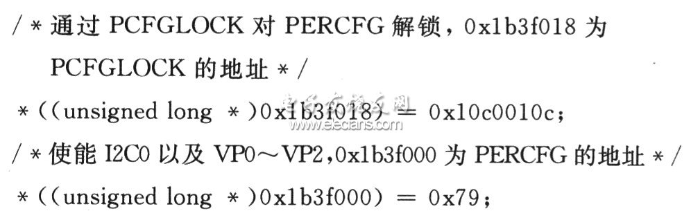
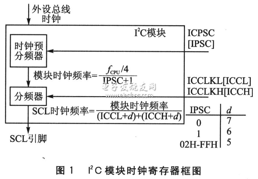
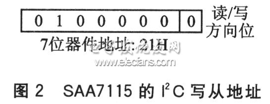
This article mainly introduces the correct initialization of the I2C module in the video acquisition and processing system based on DM642, and the correct read / write procedure of the register of the video decoding chip SAA7115 through the I2C bus. 1 Initialization of the I2C bus controller In order to correctly use the I2C module built into DM642, you need to initialize it properly. 1.1 Unlock the I2C module in DM642 In the I2C application of DM642, it is easy to encounter the problem that the initial I2C module cannot be used because the I2C module is not unlocked and enabled first. It can be seen in the data manual of DM642 that the I2C module is in a locked prohibited state after reset. That is to say, the I2CoEN bit in the hardware configuration register PERCFG is 0, so the I2C module must be enabled before configuring the I2C module control register before initialization. However, if you want to modify the contents of PERCFG, you must first write 0x10C0010C to PCFGLOCK to unlock PERCFG. To discuss and add the program to enable the I2C module: 1.2 Clock selection of I2C module After the I2C module is enabled, its control register can be initialized. The CPU clock frequency is 600 MHz, and the I2C module specifies that the module clock frequency must be selected from 7 to 12 MHz, so the I2C module clock frequency is set to 10 MHz. It can be obtained from the calculation formula in Figure 1: IPSC is OEh. Because DM642 and SAA7115 both support I2C bus 400 kbps fast mode, according to the value of IPSC, we can see from Figure 1 that d = 5. This can be set: ICCL = 7, ICCH = 8. 1.3 Problems that are easily encountered when setting the slave address It should be noted that the I2C application of DM642 often encounters the problem that the slave device cannot be read / written correctly. This is because the DM642 sets the slave address register of the I2C module differently from the I2C application of other chips. In the standard I2C protocol, the 7-bit address format of the device sends the address together with the read / write direction bits into the slave address register. However, in the application of I2C of DM642, it only needs to send the 7-bit device address to the slave address register, and the read / write direction bit is automatically generated by DM642. For example, SAA7115's standard I2C write slave address is 40H, as shown in Figure 2. The standard I2C protocol includes the address information of 21H and the last one (read / write direction bit). DM642 only needs to send 21H into the slave address register. If 40H is fed, it will cause read / write errors. 2 I2C read / write software design 2.1 Configuration mode register I2CMDR After operating on each sub-address of SAA7115, its address pointer will automatically increase, but the self-addresses of its configurable registers are not continuously distributed. Therefore, configure the I2C operating mode register (I2CMDR) to count mode. Each time I2C_write () is executed, data is transferred only once, and the initialization of SAA7115 is completed by calling I2C_write () multiple times. First write 4620H to I2CMDR. When reading the register of SAA7115, set it to non-repetitive main receiving mode, and write 4420H to I2CMDR.
Special Application safes are safes that are used in special scene and/or with special functions.
Details:
Solid steel construction;
Including data safes, medical safes and jewelry safes;
Electronic & mechanical panels are available;
Equipped with Mechanical Lock for the emergent opening of the safe
Special Application Biometric Fingerprint Treasure Safe,Intelligent Electronic Safe,Biometric Safes,Fingerprint Treasure Safe YONGFA INTELLIGENT TECHNOLOGY SECURITY CO., LTD. , http://www.yongfa-safe.com