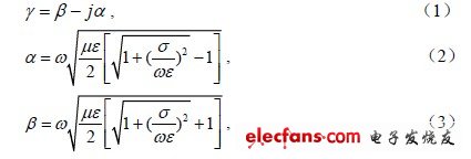
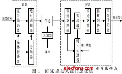
introduction Inductive communication is that after the data to be transmitted is modulated by low-frequency carrier, signal amplification, and power amplification, a certain alternating current is generated in the transmitting coil, and the alternating current is used to generate an alternating magnetic field, and the electric field generated by the alternating magnetic field, thus The induced electromotive force is generated in the receiving coil, and after filtering, demodulation, decoding and other signal processing links, the transmitted information can be accurately received at the receiving end. The low frequency induction communication system researched and designed in this paper is a wireless digital communication system. Combining the principle of DPSK digital communication, a design method of software radio low frequency induction communication system based on DSP technology is proposed, and the DPSK communication system is simulated by MATLAB . 1 The basic principle and working characteristics of low frequency induction communication 1.1 Basic principles of inductive communication Inductive communication uses the alternating current in the transmitting coil to generate a changing magnetic field to induce an electromotive force in the receiving coil, and then a series of signal processing processes to obtain the transmitted signal, thereby achieving the purpose of communication. When there is a metal conductor (called an induction line) in an occasion like a roadway, when a nearby transmitter transmits a radio signal, an induction current can be generated on the transmitter antenna. This current generates a signal field strength around the induction line. The wireless receiver antenna along the way can receive the signal due to induction. After amplification and processing, the information sent by the transmitter is obtained to complete the communication process. This is the basic principle of induction communication. 1.2 Working characteristics of inductive communication The strict theory of inductive communication is based on Maxwell's equations. Maxwell's equations are obtained through expansion and promotion on the basis of analyzing and summarizing the experimental laws of macroscopic electromagnetic phenomena. It reveals the relationship between the electric field and the magnetic field, as well as the interaction between the electromagnetic field and the charge and current, which is the general law followed by all macroscopic electromagnetic phenomena. Suppose the propagation constant of electromagnetic waves in a passive, unbounded linear, uniform, and isotropic conductive medium is: α is a constant describing the attenuation of electromagnetic waves per unit distance, called the attenuation constant; β represents the phase behind the electromagnetic wave per unit distance, called the phase constant. Where ε is the dielectric constant of the medium, σ is the conductivity of the medium, μ is the magnetic permeability of the medium, and ω is the operating angular frequency. According to the theory of electromagnetic field, in a good conductor, as the frequency increases, the attenuation constant α increases, and the attenuation of electromagnetic waves increases. In inductive communication, the lower the operating frequency, the smaller the transmission loss and the greater the coupling loss; the higher the operating frequency, the larger the transmission loss and the smaller the coupling loss. Practice has proved that the working frequency of inductive communication is 50 ~ 500 kHz. 2 Composition and implementation of 2DPSK low frequency induction communication system 2.1 Composition principle of DPSK communication system In digital communication systems, the main methods of data modulation are amplitude shift keying (ASK), frequency shift keying (FSK), and phase shift keying (PSK). Among them, differential coding phase shift keying (DPSK) Because its anti-noise performance and frequency band utilization are better than ASK and FSK, it has been widely used in actual data transmission systems. The principle block diagram of DPSK communication system is shown in Figure 1, which mainly includes three parts: modulation, channel and demodulation. The modulator adopts digital modulation, which is composed of crystal oscillator, frequency divider, differential encoder and absolute phase modulation. The crystal oscillator generates a square wave signal, and the carrier signal and clock signal required by the modulator and demodulator are respectively generated by the frequency dividing circuit. Differential phase shifting uses the relative carrier phase changes of adjacent symbols before and after to transmit digital information, differentially encodes the digital signal at the input, and then performs absolute phase modulation on the differentially encoded output to obtain a 2DPSK signal. The channel is one of the basic links of the communication system. The transmission quality of the channel affects the reception and demodulation of the signal. This effect is manifested in two ways: one is to generate noise, and the other is to weaken the signal strength and change the shape of the signal. In view of this, the DPSK signal in this design has noise superimposed during the channel transmission. There are two methods for demodulating 2DPSK signals. One is the polarity comparison method, which is the coherent demodulation method. It extracts the coherent carrier, and then transforms the relative code into an absolute code through the inverse code converter. This design uses another method, the coherent carrier method, also known as the phase comparison method or the differential demodulation method. This method does not need to restore the local carrier, just delay the 2DPSK signal by one symbol interval, and then multiply the 2DPSK signal itself After being processed by the low-pass filter, the original digital information can be recovered by sampling directly. This method can be processed with the help of FFT in DSP technology, which is simple to implement and has good performance against noise interference. Demodulation is composed of band-pass filter, multiplier, low-pass filter, sampling decision device, and differential decoder. In the absence of noise, the signal recovered by demodulation is exactly the same as the signal input by the modulator. Dc Bench Power Supply,Variable Dc Power Supply,Adjustable Dc Power Supply,Regulated Dc Power Supply Yangzhou IdealTek Electronics Co., Ltd. , https://www.idealtekpower.com