Under the premise that the current level of automobile electronics has become an important international standard for measuring the advanced level of automobiles, countries are developing this industry, constantly applying high and new technologies, and improving the performance of automobile electrification, in order to obtain a larger market. It is in this environment that stimulated and promoted the continuous development of the automotive electronics industry.
(1) There are many types of electronic regulators, and their internal circuits are different, but the working principle can be understood by the basic circuit working principle
(2) Working principle
â‘ When the ignition switch SW is just turned on, the engine does not rotate, the generator does not generate electricity, and the battery voltage is added to the voltage divider R1, R2. At this time, because the UR1 is low, the reverse breakdown of the voltage regulator VS cannot be caused, and VT1 is cut off. When VT1 is turned off, VT2 is turned on, and the magnetic field circuit of the generator is connected. At this time, the magnetic field current is supplied by the battery. As the engine starts, the speed of the generator increases, the generator separately generates electricity, and the voltage rises.
â‘¡ When the generator voltage rises above the battery voltage, the generator self-excitation generates electricity and starts to charge the external battery. If the generator output voltage UB <regulator adjustment upper limit UB2 at this time, VT1 continues to cut off, VT2 continues to conduct The magnetic field current at the time is supplied by the generator, and the generator voltage rises rapidly with the increase in speed.
â‘¢ When the generator voltage rises to be equal to the upper regulation limit UB2, the regulation of the voltage by the regulator starts. At this time, VS is turned on, VT1 is turned on, and VT2 is turned off. The generator magnetic field circuit is cut off. Because the magnetic field is cut off, the magnetic flux drops and the generator output voltage drops.
â‘£ When the generator voltage drops to be equal to the lower regulation limit UB1, VS is cut off, VT1 is cut off, VT2 is turned on again, the magnetic field circuit is turned on again, and the generator voltage rises. From beginning to end, the output voltage UB of the generator is controlled within a certain range, which is the working principle of the external ground-type electronic regulator.
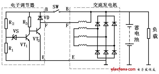
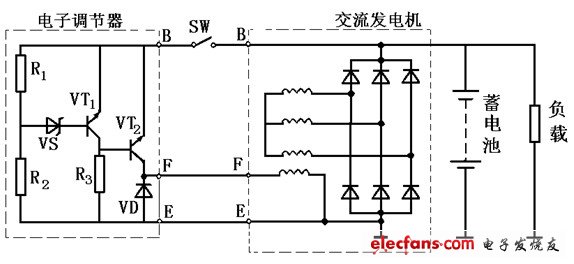
(3) The basic circuit of the grounding type electronic regulator
The basic circuit of the internal grounding type electronic regulator is characterized by the transistors VT1 and VT2 adopting the PNP type. The excitation winding of the generator is connected between the collector of the VT2 and the grounding terminal, which is significantly different from the external grounding type circuit. The working principle of the circuit And the structure is similar to the external ground-type electronic regulator.
(4) Working characteristics of electronic regulator
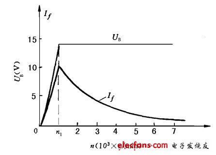
The regulator controls the magnetic field current through the switching of the triode VT2. With the increase of the speed, the on-time of the high-power triode VT2 decreases, and the cut-off time increases. This can reduce the average value of the magnetic field current and reduce the magnetic flux. Keep the output voltage UB unchanged. The relationship between the output voltage UB of the generator and the magnetic field current If (average value) with the rotation speed n is called the operating characteristic of the electronic regulator.
It can be seen from the working characteristic curve of the electronic regulator that n1 is the operating speed at which the regulator starts to work, which is called the lower operating limit. As the generator speed increases, the magnetic field current decreases. When the generator speed is very high, because the high-power transistor can not be turned on, the magnetic field current is cut off, and the generator relies on residual magnetism to generate electricity. Therefore, the upper limit of the working speed of the electronic regulator is high and the adjustment range is large.
The PufangTech UHF wireless modem operates in 400MHz to 470MHz frequency band and has a range of 1 to 10Km through buildings and up to 30Km line of sight. It transmits and receives half duplex serial data at interface baud rates of 1200bps to 115200bps with narrow band digital frequency modulation.
The configuration menu of the wireless modem can be accessed by a Windows based program running on PC. The design has been optimized for low current consumption and reliability, making PufangTech`s UHF wireless modems suitable for operation on remote sites.
Applications of PufangTech`s UHF wireless modem include SCADA, telemetry, security, command & control, data logging, remote switching or other similar applications where serial data needs to be transmitted and cable is not a practical solution.
UHF Wireless Modem,VHF Wireless Audio Modem,UHF Wireless Data Radio Modem,UHF HF Wireless Modem
Shenzhen PuFang Technology Co., Ltd. , https://www.hytelus.com