For PCB layout engineers, mobile phones present the ultimate challenge. Modern mobile phones contain almost all subsystems found in portable devices, and each subsystem has conflicting requirements. A well-designed circuit board must maximize the performance of the devices connected to it and avoid interference between multiple systems. The inconsistent requirements of various subsystems will inevitably lead to performance degradation. Despite the increasing audio functionality in mobile phones, audio circuits often receive the least attention during the circuit board design process. Here are some suggestions to help ensure a good layout without sacrificing audio quality. should -Consider the underlying planning carefully. The ideal bottom plan should divide different types of circuits in different areas. Figure 1 shows a good bottom plan. -Use differential signals whenever possible. Audio devices with differential inputs can suppress noise. Generally, the ground wire cannot be added in the middle of the differential signal. Because the most important point of the application principle of differential signals is to take advantage of the mutual coupling between differential signals, such as magnetic flux elimination and noise immunity. If you add a ground wire in the middle, it will destroy the coupling effect. There are two points to note about the wiring of differential pairs. One is that the length of the two wires should be as long as possible, and the other is that the spacing between the two wires (this spacing is determined by the differential impedance) should always remain the same, that is, keep parallel. There are two parallel ways, one is for two lines to run on the same side-by-side layer, and the other is for two lines to run on two adjacent layers (over-under). Generally, the former has more ways to achieve side-by-side. -Isolate the ground current to avoid the digital current increasing the noise of the analog circuit. Basically, it is right to separate the module / digital division. It should be noted that the signal traces should not cross the divided areas as much as possible, and the return current path of the Power Supply and the signal should not change too much. The requirement that the digital and analog signal traces cannot cross is that the return current path of the digital signal with a faster speed will try to flow back to the source of the digital signal along the ground near the bottom of the trace. If the digital and analog signal traces cross, the return current The generated noise will appear in the analog circuit area. -The analog circuit uses a star ground. The current consumption of audio power amplifiers is generally large, which may adversely affect their own ground or other reference grounds. · Change all unused areas on the circuit board to ground planes. Achieve ground coverage near signal traces to shunt excess high-frequency energy in signal lines to ground through capacitive coupling. Should not -Use a hybrid circuit on the board. Although the radio frequency region of mobile phones is generally considered to be analog, the noise coupled into the audio circuit from the radio frequency region will be demodulated into audible noise. -Analog audio signal wiring is too long. Analog audio traces that are too long may be subject to noise interference from digital and RF circuits. -Forget the importance of ground loops. Systems with poor grounding will suffer from severe distortion, noise, crosstalk, and low RF immunity. -Natural circuit for interrupting digital current. The loop area generated by this path is the smallest, which can reduce antenna effects and inductance effects. -Ignore the need to place bypass capacitors as close as possible to the power supply pins to be bypassed.
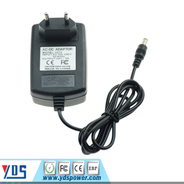
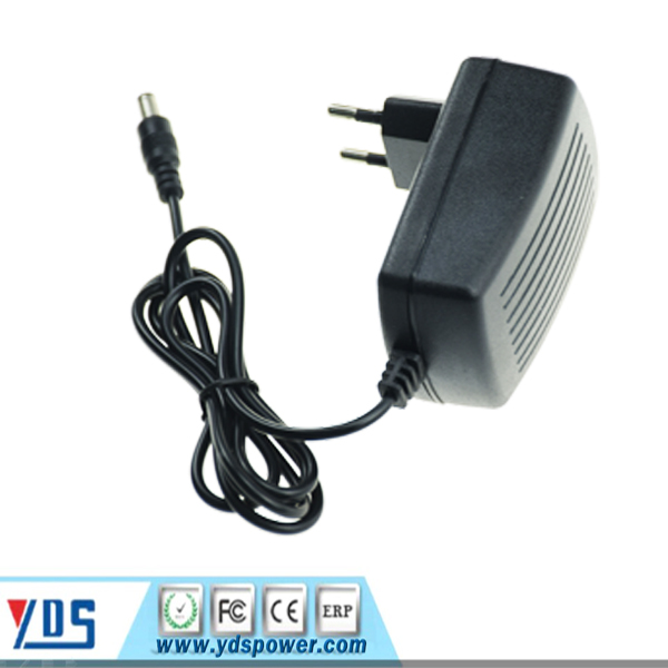
For 24 Wall Charger with different plugs for choose, the input voltage 100V~240V 50/60Hz suits for worldwide use. which are popularly used for HD player, DVD, LCD TV, surveillance camera, LED display, LED light, USB hub etc.
24V Wall Charger,Tablet Charger,24V Wall Battery Charger,24V Wall Power Charger Shenzhen Yidashun Technology Co., Ltd. , https://www.ydsadapter.com
24V Wall Mount Adapter has common 24V 500MA, 24V 1A, 24V 2A etc, the dc plug size has 5.5*2.5mm, 5.5*2.1mm and so on,
Yidashun's wall charger has intelligent protection system, to support over-current, over-voltage , short-circuit, overcharge protection etc, and Yidashun's wall mount Power Adapter has smart IC solution, high efficiency, energy saving and small ripple etc advantages.

