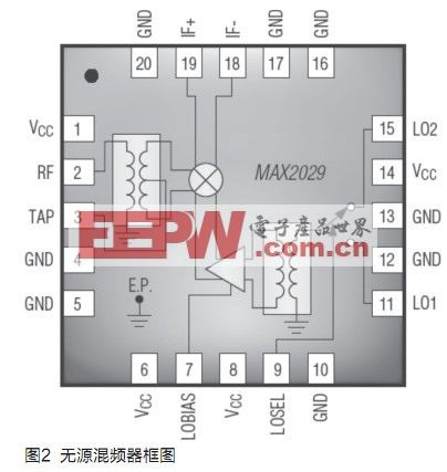
Wireless base station receiver We first analyze the block diagram of a typical receiver in a wireless base station (Figure 1). Because the received signal undergoes two consecutive down-conversions and is converted to a lower frequency, these receivers are called superheterodyne receivers. As shown in the figure, the signal is received through the antenna and then filtered by the first-stage RF filter, which is usually used to filter out unwanted signals. Subsequently, the filter output is amplified by an LNA (low noise amplifier), which usually has a very low noise figure. The amplified signal is filtered again by the second-stage RF filter, which filters out unwanted signals that limit the performance of the mixer and also limits the frequency range. After filtering, the signal with limited bandwidth is sent to the first mixer, where it is mixed with the LO (local oscillator) signal and down-converted to the IF frequency. Depending on the receiver structure, the IF signal can be further down-converted to a lower secondary IF frequency, and then sent to baseband for demodulation processing. Now, we begin to study the mixer in the receiving link. Because the main factors affecting receiver sensitivity and large signal performance are mixer parameters, they should be carefully analyzed. Mixer parameters The noise figure of the mixer represents the SNR (signal-to-noise ratio) attenuation from input to output. This ratio is usually expressed in logarithm (dB), as shown in equation (1): Another important parameter is the conversion gain (or conversion loss). The conversion gain is an important basis for judging whether the mixer is configured as an active architecture or a passive architecture. Passive mixers do not contain components that amplify signals, and there is insertion loss (called conversion loss); while active mixers contain active devices that can provide conversion gain. Two configurations can be used to implement an active mixer: an integrated mixer based on a balanced (Gilbert cell) architecture design, or a passive mixer combined with an IF amplifier stage to provide gain rather than loss. Because the integrated mixer has amplification capability, no additional IF amplifier stage is required to compensate for insertion loss. The conversion gain (or loss) is expressed in logarithm and the unit is dB. As shown in Equation 2, it is a function of frequency and is defined in the entire operating frequency range of the mixer. In order to ensure the best reception performance, the change of conversion gain / loss should be as small as possible within the specified frequency range. Since the wireless base station usually works in a temperature fluctuating environment, the specifications of the conversion gain / loss in the entire operating temperature range should be given, and the variation should be as small as possible. Under normal operating conditions, the smaller temperature variation range requires less design margin, and the design margin is very useful for system planning. Therefore, the temperature range is a very important factor in the design. The characteristics of the mixer under large signals use a mixer parameter called "1dB compression point" (the index is also called the compression point (IP1dB)) and the 2nd and 3rd order intermodulation intercept points (IP2 and IP3) Said. According to the linear expression shown in the following formula, the IP1dB compression point is used to predict the corresponding input power when the mixer gain is reduced by 1dB: When two large signals with almost the same frequency are applied to the input of the mixer, the mixer should also be able to convert weak signals. This performance is usually expressed as the third-order intercept point (IP3), which together with the noise figure represents the dynamic range of the mixer. The larger IP3 indicates that the linearity of the mixer is higher. The datasheet of the mixer should also provide the input and output intercept points of the mixer. Using equation (4), the OIP3 (output intercept point) can be calculated from IIP3 (input intercept point), and vice versa: In the formula, OIP3 is the output intermodulation intercept point of the mixer, IIP3 is the input intermodulation intercept point, and G is the conversion loss or gain. As a result, for passive mixers, the conversion loss of the mixer is reduced by OIP3. In order to achieve the overall noise figure required by the receiver, the insertion loss should be compensated at the RF or IF gain stage (noise figure is another parameter that must be considered when designing the receiver). Passive mixer and active mixer The main advantage of passive mixers is that they can also be used as upconverters. In other words, its input signal can be converted to a higher frequency. The upconverter is usually used for the transmission link, which transforms the IF signal to the final transmission frequency. Because the passive mixer can be used for both the transmit link and the receive link, only one device needs to be ordered or a device inventory is reserved. The "direct down-conversion receiver" directly down-converts the input signal to baseband without IF signal. For such receivers, the data sheet of the mixer should specify another important parameter, namely the isolation between ports. This parameter is used to measure the isolation between the LO signal and the mixer input signal. If the isolation between the ports is insufficient, the LO will mix with its own signal, resulting in a DC offset at the output of the mixer, thereby reducing receiver performance. As the mixer transforms the frequency, it will generate new frequency components (called mixer spurs). The spurious components should be fully analyzed, especially (2RF-2LO), (3RF-3LO) and higher-order spectral components, which coincide with the IF frequency and directly affect the receiver performance. This phenomenon is usually indicated by the 2 × 2 and 3 × 3 specifications in the mixer data sheet. In addition to these parameters, the degree of integration must also be considered. Integrating the mixer core with the LO amplifier, balun, and LO switch is very beneficial for some applications. Universal PCB receiver layout improves design flexibility At present, using the same circuit board layout for different frequency ranges can effectively reduce the load of development work. Only a few key components need to be modified to design the 900MHz GSM receiver system for the 1800MHz GSM system. Pin-compatible mixer series products are ideal for applications that use the same general PCB layout to support multi-band wireless architectures. The ultimate goal is to develop a circuit layout for wireless base stations of various standards, supporting GSM, UMTS, WiMAX and LTE applications. For example, in the receive link, a passive mixer similar to the MAX2029 can down-convert the received signal, while the same mixer can up-convert the IF signal in the transmit link and convert it to the final transmit frequency. All the external components are integrated in the circuit shown in Figure 2: LO buffer amplifier, balun and LO switch. As a downconverter, the MAX2029 can provide 36.5dBm IIP3, 27dBm IP1dB, 6.5dB conversion loss, and 6.7dB noise figure. Because the SiGe process of the MAX2029 greatly improves device performance, it is very suitable for base station applications that require ultra-high linearity and low noise figure. 2RF-2LO suppression (72dBc at -10dBm RF input signal) helps reduce the filtering requirements for harmonic components near the center frequency, thereby simplifying filter design and improving cost performance. The MAX2029 extends the low-end frequency range from 815MHz to 1000MHz. As part of a series of pin-compatible mixers (including the MAX2039 and MAX2041), the MAX2029 allows the receiver to use the same PCB layout to support designs with different frequency ranges and different communication standards. The active mixer can be either a balanced (Gilbert unit) design or a combination of passive mixer and IF amplifier. For example, MAX9986 uses the second configuration. The lower noise figure allows the mixer to use a very low RF gain, which helps to improve the linearity of the receiver. On the other hand, if the gain of the mixer front stage is increased in order to reduce the series noise figure, the mixer must have a sufficiently high linearity to ensure the overall linearity index of the receiver. Choose the right mixer When searching for mixers from the Internet, it is difficult to filter out all the technical index lists of different mixers, and an optimization choice needs to be made. Fortunately, we provide a web-based parameter search tool to help you complete this job. Design engineers can use the parameter search tool to quickly find the most suitable IC. All search requirements can be displayed on one webpage, and the screening results and related models are listed. Changing any search condition will immediately refresh the model list. The search function includes: click the filter box, slide filter control, multi-level filter and other prompt tools. Provides a most convenient way to find models. Heat film on Agriculture applications including : greenhouse seedling breeding Heating film, agricultural vegetable greenhouses heating film,,Seedling Heat Mat,Flowerpot heat mat etc.The application of heating film in animal husbandry, such as: hatching fowl heating film,far infrared sterilization heating film,etc.we are a professional and leader Chinese exporter of heat film,Customization options (for example: SMT components, flex cable and connectors) can provide the perfect complete solution that can significantly reduce assembly time and increase productivity.Providing a variety of complex shapes design, and different power designs. Membrane in the same piece electrically heated heating circuit can be designed and holding circuit,we are looking forward to your cooperation. Seedling Heater Tray,Electric Growing Tray for Plant,Heater Mat,Seeding Heater Mat ShenZhen XingHongChang Electric CO., LTD. , https://www.xhc-heater.com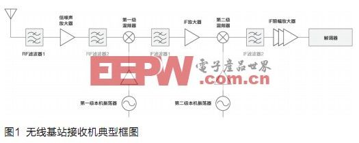

![]()
![]()
![]()
Wireless base station communication standards, such as GSM, UMTS, and LTE, define lower-limit indicators for different parameters, including receiver sensitivity and large-signal performance. These key indicators pose design challenges for each radio frequency functional module in the wireless base station. In the received signal path, mixer performance mainly affects the receiver's sensitivity and large-signal performance. The key performance and parameters of the mixer introduced in this article help to select the best mixer when designing the receiving channel.