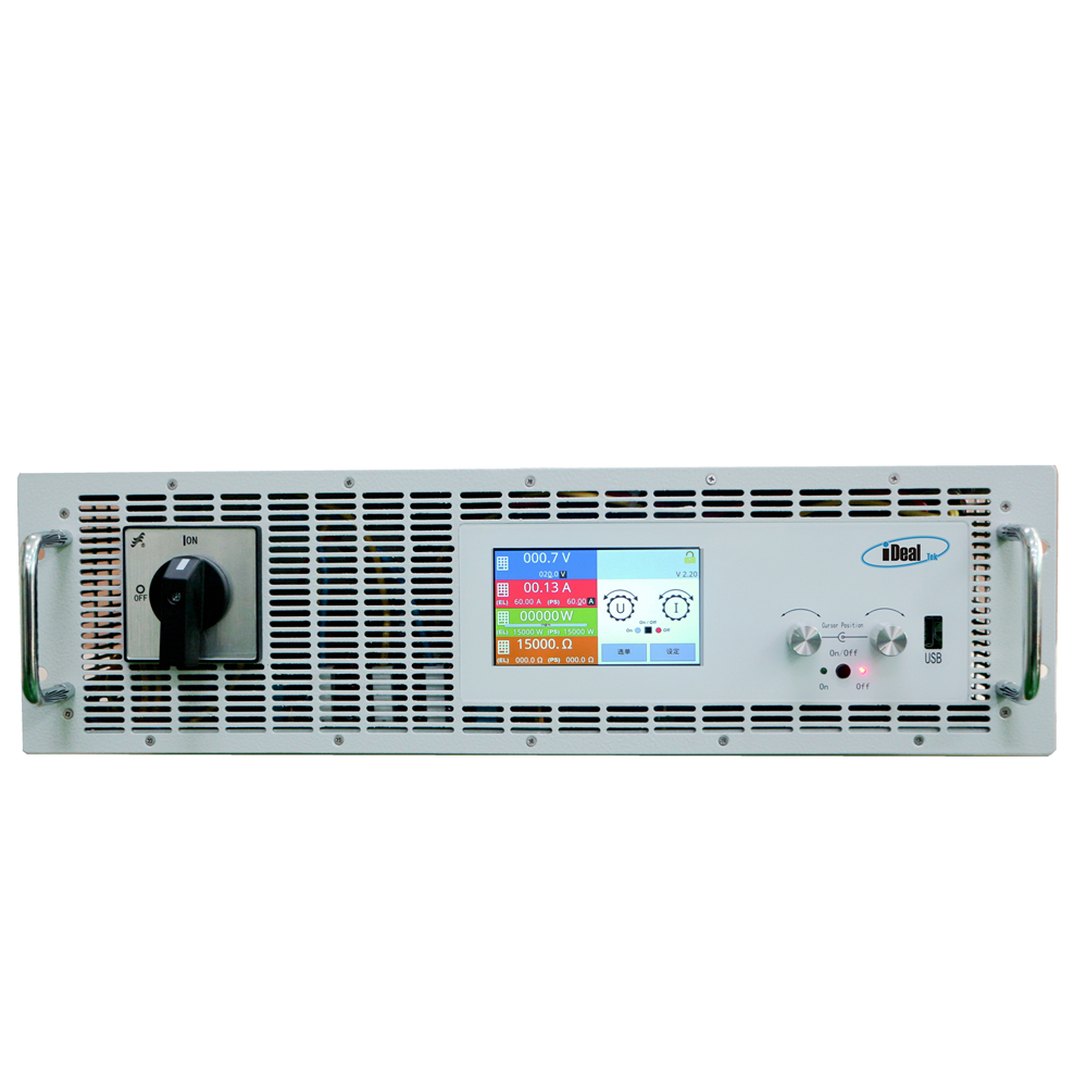
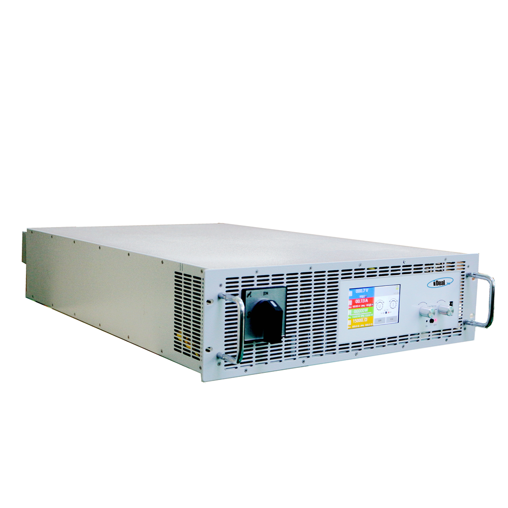
Bidirectional DC Power Supplies
The BPS series of bidirectional programmable power supplies are high-precision, low-ripple and fast response speed bidirectional DC Power Supplies with an all-digital signal control loop designed by iDealTek-Electronics based on IGBT high-frequency switching technology and bidirectional AC/DC topology architecture.
Different from the traditional DC power supply which only has constant voltage and constant current working modes, this series of programmable bidirectional AC DC power supplies have both power supply and load characteristics. It has multiple working modes of constant voltage, constant current, constant resistance and constant power, and can realize dual quadrant operation to allow the energy of the measured object to be fed back to the power supply. And Bidirectional AC-DC Power Supplies have built-in function generator, can freely generate arbitrary waveforms.
Bidirectional DC Power Supplies, Bidirectional Power Supplies, Bidirectional AC-DC Power Supplies, Bidirectional AC DC Power Supplies, Bidirectional Programmable Power Supplies Yangzhou IdealTek Electronics Co., Ltd. , https://www.idealtekpower.com


This Bidirectional DC Power Supplies are featured for high reliability, efficient setting function and complete protections, also supporting the requirement of parallel connection of multiple-units to achieve output power rating expansion, making this bidirectional power supply the best choice for the cutting-edge application industry for automated testing, automotive production line manufacturing testing, photovoltaic plate aging testing and various DC power supplies.
This series of bidirectional DC power supplies adopt active power factor correction technology, which is specially designed for typical 380V and 480V AC two-phase or three-phase alternating current with the rated output power ranging 5KW / 10KW / 15KW, the maximum output voltage ranges from 80V to 2000V under different rated powers, and the bidirectional power can be flexibly adjusted. It can output a higher voltage at a lower current or a higher current at a low voltage while maintaining within the maximum rated power range.
This article is intended for engineers who are just starting out or preparing to begin designing hardware circuits. Advanced hardware engineers may find this content too basic, and it's not necessary for them to read it. Time flies—three years have passed since I first designed my first circuit board. Just like you, when you first started touching the board, you were full of doubts and excitement. There is a lot of information about hardware design available online, covering topics like signal integrity, EMI, and power supply design, which can be overwhelming. Don't worry; everything needs to be learned step by step.
The main idea behind hardware design starts with understanding the big picture and architecture. It might seem difficult at first, but some engineers already have a framework in mind from their mentors, while others must create their own. When designing your own framework, you need to define what functions you want to implement and whether those functions can be achieved with existing components. Using reference designs (which experienced engineers often study and adapt) can save time during both pre-design and debugging phases.
If you don’t find a reference design, don’t panic. Start by selecting the main IC chip, check its datasheet, and ensure that its key parameters meet your requirements. Understanding these parameters is a crucial skill for any hardware engineer and requires long-term practice. Asking questions is essential during this learning phase, as others can help clarify things that may seem confusing to you, especially in complex areas like hardware design.
Hardware circuit design typically involves three main parts: schematic design, PCB layout, and the BOM (Bill of Materials). Schematic design converts your ideas into a visual representation of the circuit. PCB layout is where the actual physical board is created based on the schematic. The BOM lists all the components needed for the project. Tools like Altium or Protel are commonly used, and while they may differ in interface style, the core design process remains similar.
When starting out, building a component library is essential. This library defines the pin configurations and properties of each component. Protel makes this process simple, and many libraries are already available, making it easier for beginners. Understanding the difference between an IC body, pins, input/output, analog, digital, and power pins is important.
Once the library is ready, you can draw the schematic by connecting components according to the datasheet and system requirements. You’ll also learn terms like wire, line, bus, footprint, and part. After completing the schematic, generate a netlist, which acts as a bridge between the schematic and PCB design.
Before moving to PCB layout, perform an Electrical Rule Check (ERC) to catch basic errors in the schematic. Although tools can help, always double-check your work manually. Once the netlist is ready, set up the board size and define the keepout area. Consider factors like board dimensions, layer count, and laminating structure.
Component placement is crucial and affects how easy it is to route the PCB. Place analog and digital components carefully, considering power supply topology. Wiring is often done interactively with layout, and adjustments may be needed for high-speed signals. Signal integrity becomes a concern at higher frequencies, though for lower speeds, basic principles still apply.
After routing, perform a Design Rule Check (DRC) to identify any violations. Some PCBs require copper coating or teardrop shapes for vias, and the final file is converted to Gerber format for manufacturing. The BOM is then prepared, either directly from the schematic or manually using Excel for small batches.
Debugging is a critical step. Start by checking for short circuits using a multimeter. Ensure the power supply outputs the correct voltage and verify the behavior of the power chip. If issues arise, trace the problem back through the schematic and PCB. Oscilloscopes are essential for analyzing power supply stability and signal integrity.
Power supply design is one of the most critical aspects of a circuit. A stable power supply ensures the rest of the system functions properly. Two common types are LDOs (Low-Dropout Linear Regulators) and switching power supplies (PWM). LDOs offer fast transient response but lower efficiency, while switching power supplies are more efficient but noisier.
Understanding the working principles of these power supplies helps in choosing the right one for your application. For example, linear regulators are ideal for low-current, high-accuracy applications, while switching power supplies are better suited for high-efficiency scenarios.
High-speed signals are determined by the rise time of the signal rather than clock frequency. Even with a low clock frequency, if the signal edge is steep, it should be treated as high-speed. The relationship between bandwidth and rise time is governed by empirical formulas, and choosing the right oscilloscope with sufficient bandwidth is essential for accurate measurements.
In summary, hardware design is a process that combines theory, practice, and continuous learning. Whether you're working on a simple circuit or a complex PCB, attention to detail and a methodical approach will lead to successful results.