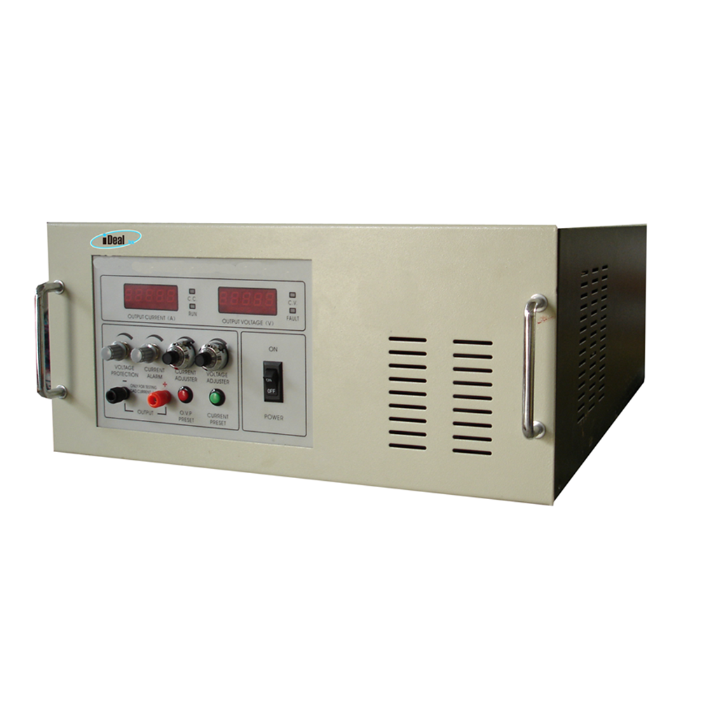
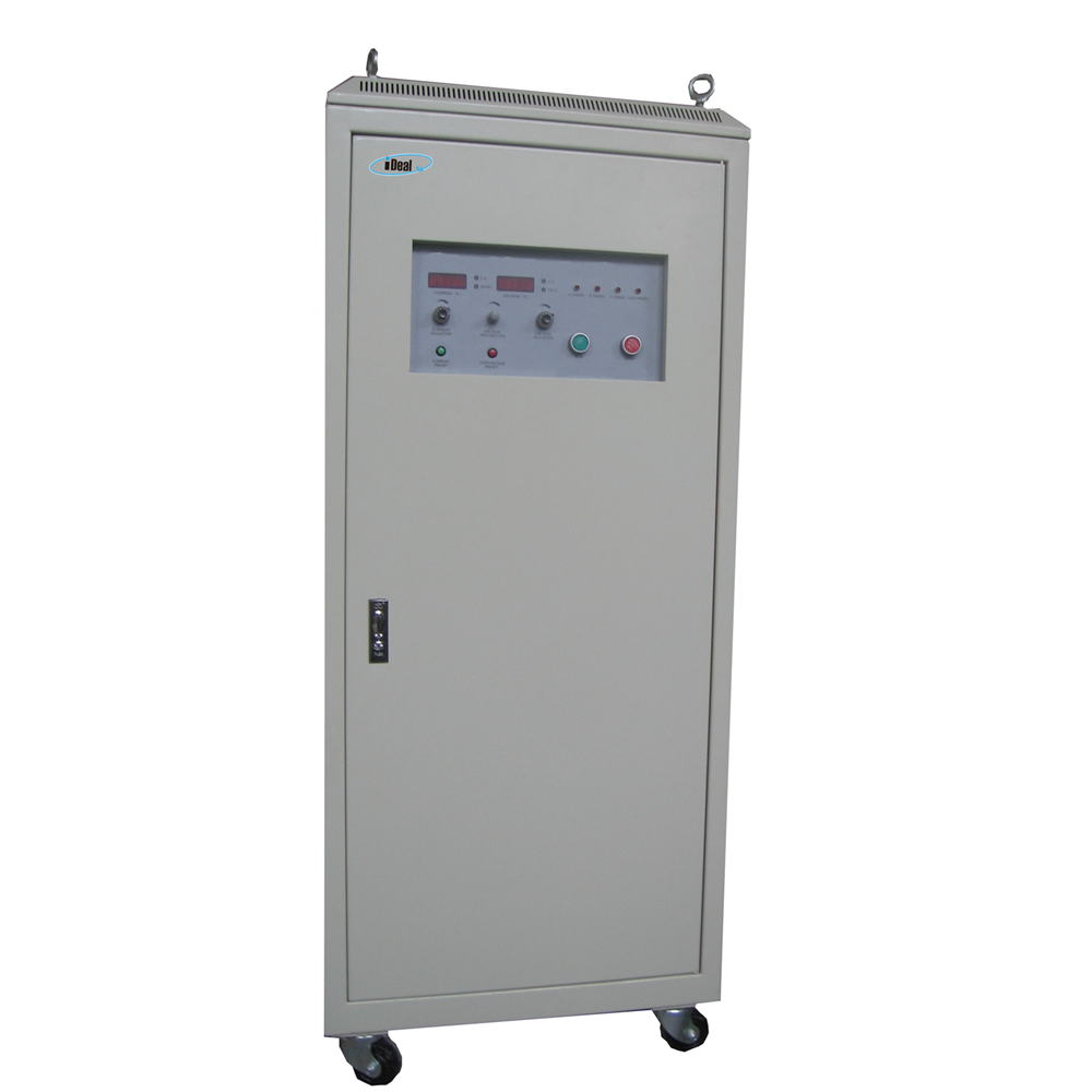
LVLP series Linear Power Supplies are DC Power Supplies that achieve AC/DC conversion through power frequency transformers and transistor loop control. Compared with switching DC power supplies, linear mode power supplies have higher stability, higher accuracy, and lower output ripple. And the most important, because of the use of the power frequency AC/DC conversion principle, the linear power supply does not have high-frequency radiation interference, and is especially suitable for use in places with restrictions on EMC and EMI.
The LVLP series linear AC - DC power supplies have a wide range of output specifications, the output power ranges from 1KW to 400KW, and the output voltage can reach up to 800VDC, and accept customization.
Linear DC Power Supplies, Linear AC - DC Power Supplies, DC Linear Power Supplies, AC - DC Linear Power Supplies, Linear AC DC Supplies Yangzhou IdealTek Electronics Co., Ltd. , https://www.idealtekpower.com


The whole series DC linear power supply adopts industrial-grade metal chassis, pure copper AC/DC varnished transformer, high-reliability multi-transistor filter loop, ensuring the power supplies can run for a long time at full load with high stability, high accuracy, and ultra-low ripple electronic characteristics, equipped with a complete protection circuit, which can better ensure the reliability of the linear power supply itself and the safety of the customer's load.
The output voltage and current can be adjusted by the 10-turn potentiometer with scale and lock on the front, equipped with 4 1/2-digit high-resolution LED meters for output value reading, and RS communication interface can also be added for remote control and monitoring of linear power supplies.
This series of linear power supplies are mainly used for aging and testing of components such as capacitors, relays, and resistors, and can also be used for experimental testing of electronic components such as thermistors and motors. At present, many well-known capacitor manufacturers, resistor factories and other electronic component production units and scientific colleges and universities and other research and development units use this series of power supplies, and they have all been highly praised.
This article is intended for engineers who are just starting out or preparing to dive into hardware circuit design. Experienced high-level hardware engineers may not find it necessary to read this. Time flies, and it's been three years since I first drew my first circuit board. Like you, when I first touched the board, I was full of questions and excitement. There's a lot of information online about hardware circuits, covering topics like signal integrity, EMI, and power supply design — all of which can be overwhelming. Don’t worry; everything takes time to learn and understand.
The main idea starts with the big picture. When designing hardware circuits, you need to figure out the overall architecture and framework. It’s not easy, especially if you're doing it from scratch. Some engineers work under the guidance of more experienced mentors who handle the big decisions, while others have to design their own frameworks. In such cases, you must determine what functions you need and whether you can achieve them. Using reference designs is a great way to learn from others' work, and experienced engineers often use these as a foundation.
If you find a reference design, that's great — it can save you a lot of time in both pre-design and post-debugging. But don’t rush to copy it directly. Take the time to understand it. This helps improve your circuit knowledge and prevents mistakes during your own design.
If you can't find a reference design, don’t worry. Start by selecting a key IC chip and check its datasheet. Make sure its key parameters meet your requirements. Understanding those parameters is a crucial skill for hardware engineers, and it takes time to build up. During this learning phase, don’t hesitate to ask questions — someone else might clarify things in a single sentence, especially in hardware design.
Hardware circuit design generally consists of three parts: schematic design, PCB layout, and the BOM (Bill of Materials) table. The schematic translates your ideas into a circuit diagram, similar to what you see in textbooks. PCB involves placing components on the board and connecting them according to the netlist, which acts as a bridge between the schematic and the physical layout. Finally, the BOM lists all the components needed for the project.
For tools, Protel (now known as Altium Designer) is widely used in China and is user-friendly for beginners. While more complex tools like Cadence are also available, the core process remains the same. Whether you use Protel or Cadence, the design principles are similar, though the interface and workflow differ.
There are three major steps in the design process: 1) Creating the schematic library, 2) Drawing the schematic, and 3) Generating the BOM. First, you need to create component libraries, which define the pin configurations and properties of each part. Then, connect components based on the datasheet and system requirements. Add notes and annotations where necessary. Understand the difference between wires (which carry electrical signals) and lines (used for graphics). Learn terms like bus, footprint, and part.
After completing the schematic, generate a netlist to transfer the design to the PCB. Before proceeding, perform an Electrical Rule Check (ERC) to catch any basic errors. Next, draw the PCB, considering the board size, layer stackup, and placement of components. Layout is critical, as it affects how easily you can route the signals. Pay attention to analog vs. digital isolation, power supply topology, and mechanical constraints.
Wiring is the next step, often done interactively with layout adjustments. For high-speed designs, signal integrity becomes a concern, but for most projects, following basic rules suffices. After routing, perform a Design Rule Check (DRC) to ensure no violations exist. Finally, prepare the BOM and send the Gerber files to the manufacturer.
Assembling the PCB requires careful handling of the BOM. Beginners should avoid handing over the entire list to the factory immediately. Instead, assemble and test components one by one after the board arrives.
Debugging is a crucial part of the process. Start by checking for short circuits using a multimeter. Ensure the power supply is stable and functioning correctly. If there's an issue, trace the problem back through the schematic and PCB. Use an oscilloscope to monitor voltage fluctuations and signal behavior.
Power supply design is the most critical aspect of any circuit. A stable power supply ensures the rest of the system works reliably. Two common types are LDOs (Low-Dropout Linear Regulators) and switching power supplies (PWM). LDOs offer fast response and low noise, while switching supplies are more efficient. Understanding their working principles helps in choosing the right solution for your design.
High-speed signals aren’t defined by clock frequency alone. Even with a low-frequency clock, a fast edge can make a signal high-speed. The rise time determines the bandwidth, and understanding this relationship is essential for accurate signal analysis.
When selecting an oscilloscope, focus on bandwidth rather than sampling rate. A scope with at least three times the signal bandwidth is usually sufficient. Also, remember to account for probe limitations, as they can affect measurement accuracy.
In summary, hardware design is a process that combines theory, practice, and patience. By following best practices and continuously learning, you'll become a more confident and capable engineer.