1. Introduction
Massive MIMO (massive multiple-input multiple-output) is one of the core technologies in 4.5G and 5G networks, attracting significant attention from the global telecommunications industry. China Mobile and SoftBank Japan have already deployed TD-LTE Massive MIMO technology, while operators such as China Unicom, China Telecom, and Telkomsel have completed field trials of FDD Massive MIMO. Massive MIMO was also a key technology in the first phase of China's 5G trials, with five vendors including Huawei, ZTE, and Ericsson participating. The 3GPP standard has supported Massive MIMO as an essential feature since the R13 release, signaling its importance in future communication systems.
Massive MIMO leverages a large number of antenna elements—such as 64, 128, or 256—to significantly increase wireless data traffic and improve connection reliability. Compared to traditional single- or dual-polarized antennas and 4/8-channel systems, large-scale antenna technology enhances spectrum and energy efficiency through multiple dimensions, including space, time, frequency, and polarization. Advanced 3D beamforming and channel estimation techniques allow for adaptive adjustment of each antenna element’s phase and power, improving beam accuracy and concentrating signal strength on specific users or areas. This not only enhances user signal quality but also reduces self-interference and inter-cell interference, ultimately boosting the carrier-to-interference ratio.
Evaluating the performance of Massive MIMO technology involves identifying appropriate test indicators and methods. How to fairly and efficiently measure this technology remains a critical issue that the industry is actively addressing.
2. Massive MIMO System Architecture
The active antenna base station architecture supporting Massive MIMO typically includes three main functional modules: a radio frequency transceiver unit array, a radio frequency distribution network (RDN), and a multi-antenna array.
The RF transceiver unit array consists of multiple transmit and receive units. The transmit unit processes the baseband input and generates a radio frequency output, which is then distributed to the antenna array via the RDN. The receive unit performs the opposite function. The RDN distributes the output signals to the corresponding antenna paths and elements and routes incoming signals back in the reverse direction.
In some configurations, the RDN may involve a direct one-to-one mapping between the transmit/receive units and the passive antenna array. In such cases, the RDN functions more as a logical entity rather than a physical one.
Antenna arrays can be implemented in various forms, including different polarizations and spatial separations. The physical layout of the RF transceiver unit array, RDN, and antenna array may differ from their logical representation, depending on the system design.
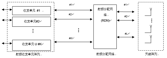
Figure 1: Active antenna base station architecture supporting Massive MIMO
3. Massive MIMO Test Technology
3.1 Evolution of Antenna Systems and Testing Challenges
As antenna systems evolve toward modernization, especially with the advancement of 5G, the integrated active antenna system (AAS) has become increasingly popular. With more channels and simplified active antenna connections, the integration of RU and antenna has led to new challenges in testing. Traditional conduction tests are no longer sufficient, and over-the-air (OTA) testing is becoming a necessary direction, though it brings complex challenges.
Table 1: Evolution of Antenna Systems and Testing Challenges
| Antenna System Type |
Features |
Test Method |
Supports Conduction Test? |
Testing Challenges |
| RRU + Antenna |
Separate design, independent manufacturing, defined RF performance at the base station port, no consideration of antenna impact. |
Independent testing of RRU and antenna |
Yes |
Mature technology, no major issues. |
| Integrated Active Antenna |
Highly integrated, non-standard interface, RF performance defined at the antenna port, increased need for OTA testing. |
Integrated + split testing |
Yes, non-standard interface |
Non-standard conduction interface, limited reflection of performance, need for clearer OTA standards. |
| Massive MIMO Antenna |
Deep integration, large-scale antenna, OTA testing proposed by 3GPP. |
Mainly machine testing |
Depends on system design |
Difficult to disassemble, requires extensive OTA testing, standards still under discussion. |
3.2 Test Signal Modulation
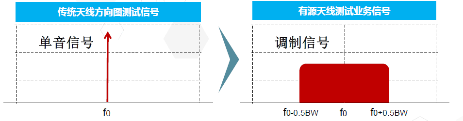
Figure 2: Test Signal Modulation
To evaluate the performance of active antennas, the test system must support amplitude and phase testing of service signals, especially for high-bandwidth signals. It should also define appropriate test patterns.
3.3 Antenna Beam Diversification
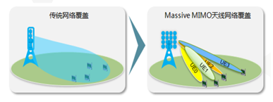
Figure 3: Schematic of Massive MIMO Antenna Network Coverage
In scenarios where beam radiation characteristics are complex, it is crucial to accurately assess beam direction, side lobes, and beam width. Selecting test scenarios for multi-beam systems and improving test efficiency for multi-beam antennas are also important. Additionally, evaluating two-dimensional radiation characteristics and coverage performance is essential.
Recommendations:
1. Evaluate active antennas, especially Massive MIMO, under two main planes and study 3D radiation requirements.
2. Establish test case sets for multi-beam radiation performance under real service signals.
3.4 High Frequency Communication Antennas
High-frequency (millimeter wave) coverage has long been a challenge in the industry. Massive MIMO offers a promising solution, providing capacity guarantees as part of 5G's extended frequency bands. However, higher frequencies result in shorter coverage distances. While increasing the number of antenna elements can compensate for this, it also increases costs. Reducing antenna costs is therefore a key issue for 5G multi-antenna technology.
As a key component of 5G evolution, high-frequency Massive MIMO antennas feature high frequency, large bandwidth, and ultra-large-scale arrays. These characteristics require new approaches to testing, including re-defining high-frequency radiation indices, supporting large-diameter UHF antenna testing, and enabling ultra-wideband signal testing.
3.5 RF Indicator Test Over-the-Air (OTA)
With the deep integration of antennas, especially in Massive MIMO systems, testing RF indicators becomes increasingly challenging. There is currently no clear technical approach, and 3GPP is still discussing standards. One direction is OTA testing, but defining and measuring air interface performance remains a difficult problem.
Currently, 3GPP R13 defines EIRP and EIS as air interface indicators, while R14 addresses other metrics. However, the exact method for OTA testing of these indicators is still under research, with no clear consensus yet.
Two main categories exist:
a) In-band indicators: If antenna performance is known, existing OTA test plans can be used.
b) Out-of-band indicators: Testing out-of-band performance is a significant challenge due to the wide-band nature of the signals.
3.6 3D Beamforming Characteristics
Using 3D beamforming for accurate channel estimation reveals limitations in describing beam characteristics using traditional 2D sections. As shown in the figure, conventional E and H-plane cuts do not fully capture the sidelobe distribution. Moreover, the service beam of a Massive MIMO antenna changes dynamically with user positions, making it impractical to test all possible scenarios. Therefore, selecting typical business scenarios for testing is recommended.
Compared to traditional antennas, Massive MIMO may offer narrower beams, and the accuracy of beam pointing directly impacts network coverage. Evaluating beam pointing precision is therefore crucial. Additionally, the ability to split multiple beams per antenna array is an important indicator of network coverage performance, and user throughput under these beams should also be evaluated.
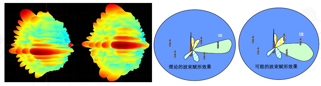
Figure 4: Beamforming Characteristics
4. Summary
As networks continue to evolve, antenna and RF modules will become more deeply integrated, making Massive MIMO active antennas the mainstream in future development. Integrated testing and OTA testing are expected to dominate the testing landscape.
Compared to traditional testing methods, the test indicators, evaluation systems, principles, and platforms for Massive MIMO face major challenges. These innovations could lead to unprecedented advancements in mobile communication systems, requiring ongoing exploration and development.
Transparent Led Screen
transparent LED screens offer a unique and visually striking way to display content while maintaining transparency and visibility. They have gained popularity in recent years and are continuously evolving with advancements in LED technology. Transparent LED screens can be used both indoors and outdoors, depending on the specific model and its level of weather resistance. They are typically lightweight and easy to install, with options for wall-mounted, freestanding, or suspended installations.
Hot-selling serie is P3.91 1000*500mm/1000*1000mm.
Transparent Led Screen,Led Wall Display,Building Led Display Panel,Sport Led Screen
Guangzhou Cheng Wen Photoelectric Technology Co., Ltd. , https://www.cwledwall.com