Advantage
* Nova MSD 300 sending card and Nova mrv328 receiving card
* Cabinet size:640x1920mm
* Kinglight/Nationstar LED Lamp, Refresh rate:1920-3840hz
* High brightness up to 2000cd/sq.m, even in the sunlight conditions can see clear, but low power consumption to save the electric power cost.
* High debugging brightness and no damage to gray scale, achieving the debugging technology for nice image.
* Passed the TÃœV,FCC,ROHS,CE cetification.
Poster LED Display,Poster Led Display Screen,Mirrior Led Display,Led Poster Display Guangzhou Chengwen Photoelectric Technology co.,ltd , https://www.cwleddisplay.com
1. Utra Thin and Light weight, Cabinet weight only 19KG and 86mm thickness.
2. In direct sunlight, the outdoor LED Display can be high-definition and high-brightness, high refresh rate, high contrast
3. Can withstand high and low temperature, can be used in extremely harsh environment
4. Modular design, Front and Rear maintenance system available, Separate and exchangeable power and data unit can be easily removed for easy maintenance
5. Outdoor IP65 is waterproof, dustproof and corrosion proof, ensures smooth and reliable operation under variable and extreme weather conditions.
**What is PLC Programming?**
PLC, or Programmable Logic Controller, is a fundamental control method widely used in industrial automation. It can be implemented through small-scale devices or large integrated systems and can interact with human-machine interfaces (HMIs) as well as communicate with computers. Initially designed to replace relay control circuits, PLCs have evolved into multi-functional, integrated controllers capable of handling basic operations such as timers, counters, analog inputs, and outputs through their CPU units. Essentially, a PLC functions like a microcontroller, used for electrical control in various industrial applications.
**Working Principle**
The PLC operates using a "sequential scanning, continuous cycling" approach. When the PLC is running, the CPU executes a program stored in user memory according to the control requirements. It performs periodic, cyclic scans based on instruction step numbers (or addresses). If there are no jump instructions, it starts from the first instruction, executes the user program sequentially until the end, and then loops back to the beginning for the next scan. During each cycle, the PLC samples input signals and updates output states.
A single PLC scan cycle consists of three stages: input sampling, program execution, and output refresh. During the input sampling phase, the system reads the on/off state or data from all input terminals, stores them in the input latch, and updates the input status registers before closing the input ports and moving to the program execution stage.
In the program execution phase, the PLC processes each instruction in the order they are stored in the user program. After performing the necessary operations, the results are written to the output status registers, which are then updated accordingly.
During the output refresh phase, the PLC sends the on/off status of the output status registers to the output latches, which drive the corresponding output devices (such as relays, transistors, or thyristors) to perform the required actions.
**Characteristics**
PLC programming has broad applications, powerful functionality, and ease of use. It has become one of the core components of modern industrial automation and is widely used across all sectors of industrial production, including civil and home automation. Its development has been rapid, especially in China, where it has been extensively applied in mechanical equipment and electrical control systems.
According to the 1985 IEC standard, a PLC is defined as an electronic system for digital operations, designed for use in industrial environments. It is programmable, with memory used to store instructions for logic operations, sequence control, timing, counting, and arithmetic processing. The system controls various mechanical or production processes through digital and analog inputs and outputs. PLCs are designed to integrate easily into industrial control systems and support future expansion.
Understanding the working principle of PLCs and having the ability to design, debug, and maintain PLC control systems have become essential skills for electrical technicians and engineering students in modern industry.
**PLC Programming and Application in Practice**
With numerous PLC programming software options available, this paper uses the commonly used Siemens STEP 7-Micro/WIN as an example to demonstrate how to write PLC control programs.
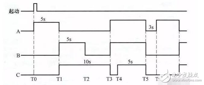
**1. Fountain Control**
1) Clarify System Control Requirements
The system requires two buttons to control three groups of nozzles (A, B, C), each controlled by a pump motor. The nozzles are arranged as shown below.
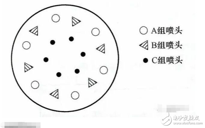
The control sequence is as follows:
- Pressing the start button activates nozzle A for 5 seconds, then stops.
- Nozzles B and C spray together for 5 seconds.
- Nozzle B stops, while C continues for another 5 seconds.
- Then, A and B spray for 7 seconds, during which C stops after 2 seconds.
- All nozzles stop for 3 seconds, and the cycle repeats.
- Pressing the stop button halts all nozzles immediately.
2) Identify Input/Output Devices and Assign I/O Terminals
The following table shows the input/output devices and their corresponding PLC terminals for fountain control.
3) Draw the Fountain Control Circuit Diagram
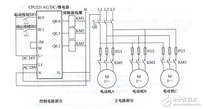
*Control Circuit Diagram*
4) Write the PLC Control Program
Using the STEP 7-Micro/WIN software, a ladder diagram was created to meet the control requirements. The final ladder diagram is shown below.
*Ladder Diagram*
The operation of the ladder diagram is explained in reference to the control circuit and timing diagram.
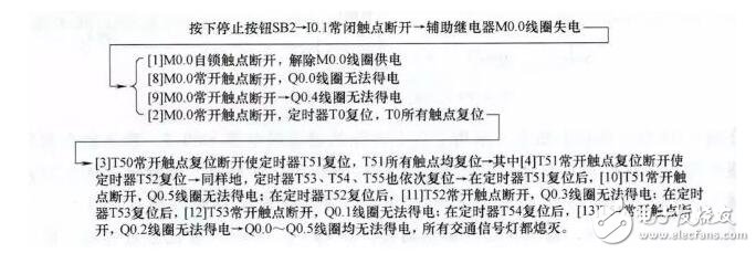
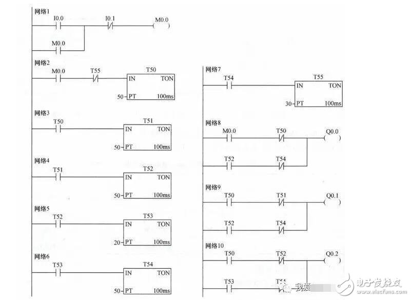
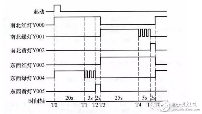
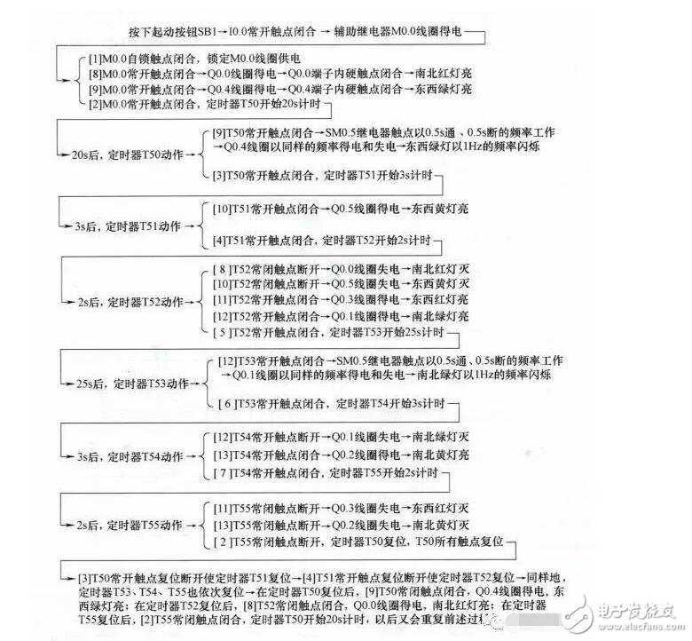
**2. Traffic Signal Control**
1) Clarify System Control Requirements
The system uses two buttons to control traffic lights, as shown below.
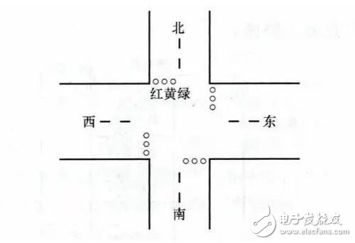
The control sequence is as follows:
- Pressing the start button turns on red lights for north and south for 25 seconds.
- East and west green lights turn on for 20 seconds, then flash three times at 1 Hz.
- East and west yellow lights turn on for 2 seconds.
- North and south red lights go out, and the red light for east and west remains on for 30 seconds.
- Then, north and south green lights turn on for 25 seconds, flash three times at 1 Hz, followed by yellow lights for 2 seconds.
- The cycle repeats.
- Pressing the stop button turns off all lights.
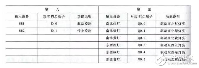
2) Identify Input/Output Devices and Assign I/O Terminals
The following table shows the input/output devices and their corresponding PLC terminals for traffic signal control.
3) Draw the Traffic Signal Control Circuit Diagram
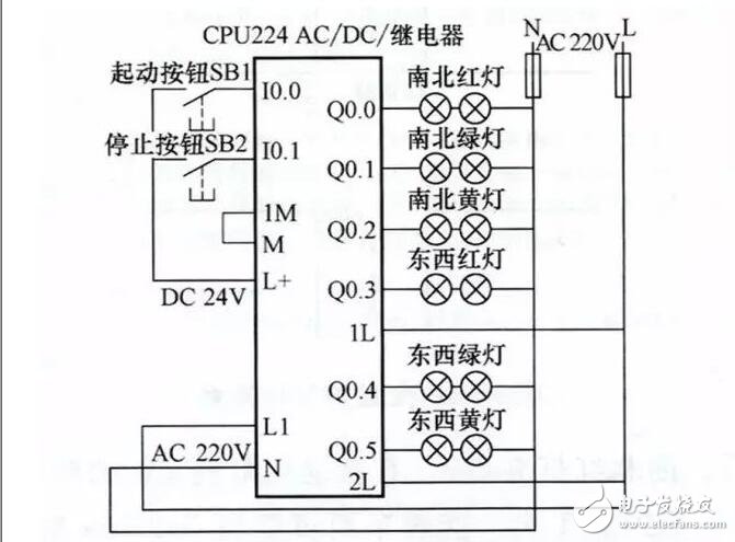
*Control Circuit Diagram*
4) Write the PLC Control Program
Using the STEP 7-Micro/WIN software, a ladder diagram was created that meets the control requirements. The final ladder diagram is shown below.
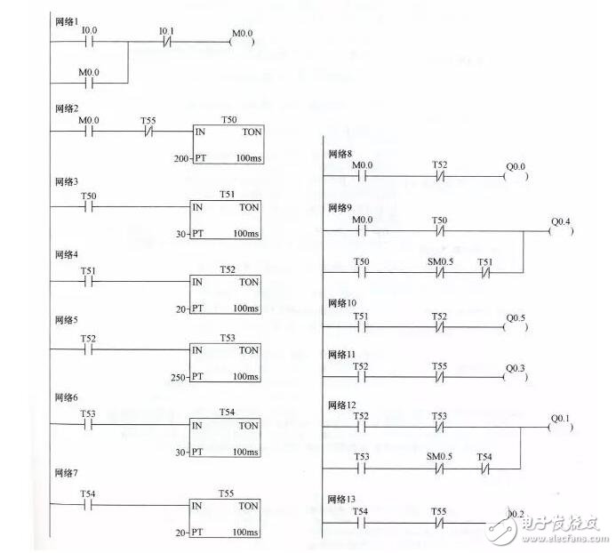
*Ladder Diagram*
The ladder diagram uses the special auxiliary relay SM0.5, which generates a 1-second clock pulse with 0.5 seconds high and 0.5 seconds low. This allows for precise timing in applications like flashing lights.
The operation of the ladder diagram is explained with reference to the control circuit and timing diagram.
**1) Start Control**
**2) Stop Control**