This article will introduce the many challenges and latest developments in electronic design of different imaging methods, including digital X-ray, magnetic resonance imaging (MRI) and ultrasound systems.
Digital X-ray system
Traditional X-ray systems use a film / screen device to detect X-rays emitted into the human body. However, the digital X-ray signal chain in the detector system contains a photo detector array that converts the radiation into electrical charges. It is followed by some charge integrator circuits and analog-to-digital converter (ADC) circuits to digitize the input. Figure 1 shows an example of a typical digital X-ray system structure diagram.
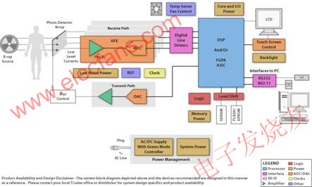
Figure 1 Example of a digital X-ray system structure diagram
The performance of the digital X-ray system is closely related to the noise performance of the integrator and ADC module. In order to obtain higher image quality under low power consumption, the degree of electronic integration required to support a large number of signal channels in a system sets a certain standard for technological innovation. It is because of the many high-performance analog components that make up the detector system and the embedded processor that performs advanced image processing tasks that the X-ray system has many advantages over traditional X-ray systems. This combination supports a greater dynamic range, which results in better image contrast and lower patient X-ray radiation levels, while producing digital images that can be electronically stored and transmitted.
Ultrasound system
The receive channel signal chain of the ultrasound system includes a low-noise amplifier (LNA), a variable gain amplifier (VGA), a low-pass filter (LPF), and a high-speed high-precision ADC. Following these components are digital beamforming, image and Doppler processing, and other signal processing software (see Figure 2).
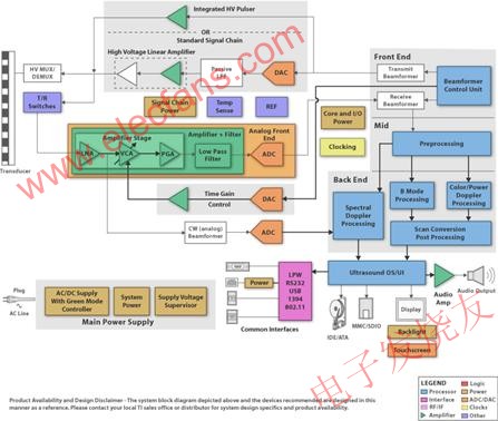
Figure 2 Example of an ultrasonic system structure diagram
The noise and bandwidth characteristics of the signal chain components define the overall upper performance limit of the system. In addition, while dissipating lower system power, more high-performance channels need to be integrated in a smaller area. A typical handheld ultrasound system may have about 16 to 32 channels, while some high-end systems may have more than 128 channels to obtain higher image quality. To reduce the number of printed circuit boards (PCBs) that occupy all of these array channels, the emphasis is on integrating as many channels as possible in the analog front-end IC. The total system power consumption is another important performance index for handheld systems. Integrating the receiver electronics directly into the probe is another aspect of innovation.
Doing so helps shorten the distance between the low-voltage analog signal source and LNAs in the probe, thereby reducing signal loss. Integration will further increase the number of probe pieces, thereby enhancing 3D imaging. In addition to these analog signal chain considerations, high-performance, low-power embedded processors can complete beamforming and image processing tasks for portable devices faster and more efficiently than before.
MRI
For an example of a typical MRI channel analog signal processing chain, see Figure 3.
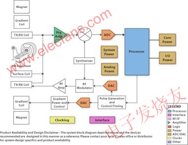
Figure 3 MRI system structure diagram example
A whole-body MRI system may have a coil matrix of up to 76 elements or channels. In addition, a low voltage (LV) analog input is transmitted along the long coaxial cable from the limb coil to the analog signal chain preamplifier. When it comes to the MRI receive signal chain, two keys come up: how to obtain a high signal-to-noise ratio (SNR) (at least about 84dB or 14 bits); how to achieve the extremely high total dynamic range of the total system (at least 150 dB / Hz) about). Obtaining high SNR requires a high-performance preamplifier with ultra-low noise figure. The use of innovative solutions such as dynamic gain adjustment or analog input compression can achieve high dynamic range requirements.
In short, by increasing the number of coils used in the MRI system, not only can a better image range be obtained, but also the image scanning time can be shortened. The increase in the number of coils may require further optimization of the signal communication between the coil and the preamplifier, while the use of high-speed digital or optical links requires further optimization of the main system. In addition, a high degree of integration will lead to a system division that is different from the current, which may bring electronic devices closer to the coil. In this regard, semiconductor ICs may require non-magnetic packaging and comply with more stringent power and area regulations. The successful implementation of the above requirements can reduce the attenuation of the input signal, thereby obtaining higher quality medical images.
to sum up
Digital imaging is one of the most active areas of technology development in the medical industry today. The tremendous progress made by IC analog / mixed-signal functions and various embedded processing is continuously promoting its development. The emergence of these technologies has improved the performance of imaging systems, while also greatly improving the quality of diagnosis and medical care services for patients.
Li-ion Battery With SMBUS refers to the battery datas can be collect through equipments based on SMBUS data communication, it usually applied to the military grade battery which need higher safety level protection .but as these battery have SMBUS inside ,it also should meet these requirements as :
1.The rated voltage is high (the operating voltage of the unit is 3.7v or 3.2v), which is about equal to the series voltage of three nickel-cadmium or nickel-hydrogen charging batteries, so as to form the battery power supply group
2.The self-discharge rate is very low, which is one of
the most prominent advantages of the battery. At present, it can reach less
than 1% per month, less than 1/20 of the nickel hydrogen battery.
14.8V Li-Ion Battery With Smbus
Items specification
Charge voltage : 16.8V
Nominal voltage : 14.8V (4S4P)
Initial impedance : 200mΩ
Nominal capacity: 10.4Ah
Minimum capacity : 10.0Ah
Communication methods : SMBUS data communication
Charge current : Standard Charging::0.5C5A (5.20A
Rapid charge 1.0C5A C(10.4A) Max
Standard Charging method: 5.20A(0.5C5A) CC(constant current)charge to 16.8V,then CV(constant voltage 16.8V)charge till charge current decline to ≤104mA(≈0.01C5A)
Charging time: Standard Charging:4.5hours(Ref.)
Rapid charge: 2.5 hours(Ref.)
Max.discharge current: 10.4A(1.0C5A)
Discharge cut-off voltage: 11.0V
Shelf life: 2 years
Cycle life (0.2C5A/0.2C5A) : 500 times,≧80%DOD; 500 times,≧80%DOD

Li-ion Battery With SMBUS
Li-Ion Battery With Smbus,Lipo Battery,Battery Pack With Smbus,Smart Li-Ion Battery Pack With Smbus
YFJ TECHNOLOGY (HK) CO.,LIMITED , http://www.yfjpower.com