With the advent of computer network technology, multimedia technology, computer vision and pattern recognition technology, a multimedia remote digital monitoring system featuring digitalization and intelligence has emerged. The IP-based digital monitoring system has realized the traditional A leap from analog monitoring to digital monitoring. Compared with the traditional analog monitoring system, the most important advantages of the digital remote monitoring system are: remote monitoring can be realized through the network; the remote control center or the same branch control center at different locations can watch a certain one or several at the same time. A monitoring site audio and video data, so as to achieve distributed audio frequency access and audio and video data sharing, at the same time, can talk to the monitoring site personnel; can control the remote monitoring site PTZ, camera and other peripheral equipment. Real-time, distributed transmission of video and audio and reliable transmission of control commands are a key issue in remote digital monitoring systems. This article designs and implements a remote digital audio frequency monitoring system, adopts IP MulTIcast technology as a distributed audio and video persistent access and sharing solution, and aims at different characteristics of video, audio, voice and control data, and adopts different transmission technologies for it Have carried on the discussion, has given the concrete realization method. 1 The overall structure of the system The remote monitoring system generally includes three parts: front-end monitoring site, communication equipment and back-end branch control center. The entire system is based on the Client / Server mode. The overall structure is shown in Figure 1. (1) The front-end monitoring site consists of the monitoring site host and some peripheral equipment. Peripheral equipment includes cameras, motorized lenses, gimbals, protective covers, monitors, multi-function decoders and alarms. The monitoring field host runs the customer's front-end software to realize real-time collection, compression, and decompression (audio) of video and audio data (video transmission is unidirectional, audio transmission is bidirectional) and packaged transmission; Perform warp storage (can also be carried out in the near center). The storage method is circular storage, timing storage, manual storage and motion video detection start storage. Receive control commands from the sub-control center (can also be implemented locally), three variable (iris, focal length and focus) of the PTZ motion (up, down, left, right and automatic) electric lens. (2) Communication equipment refers to the adopted transmission channel and related equipment, and the communication network is LAN and WAN. (3) The back-end equipment is composed of several branch control center computers. Each sub-control computer runs server-side software, receives compressed video (audio) frequency and display (playback) from the front end; controls the front-end PTZ and camera through the network; adopts multicast technology to achieve distributed video attachment and split-type Video sharing: each sub-control center host can monitor multiple front-ends at the same time, that is, "point-to-multipoint"; different sub-control centers can also monitor the same front-end at the same time, that is, "multipoint-to-point". 2.1 The characteristics of the type of data transmitted by the system and the choice of communication protocol The system transmits data: control data, audio, video data, and the back-end sub-control center sends control signals to the PTZ and camera of the monitoring site host peripheral equipment through the network to realize the PTZ motion (up, down, left, right, automatic) camera The aperture, focal length, and focus are variable, requiring accurate transmission of control signals; audio and video are continuous, and the amount of data is large, allowing a certain data error rate and data loss rate during transmission, but the real-time requirements are high. In addition, in the monitoring system, to achieve distributed access of audio and video and data sharing, multipoint transmission of audio and video must be carried out. How to achieve the above goals? The first is the choice of communication protocol. TCP / IP is a widely used network protocol. Its network model defines four layers (ie, network interface layer, network layer, transport layer, and application layer) network communication protocol. The transport layer contains two protocols: Transmission Control Protocol (TCP) and User Datagram Protocol (UDP). IP is an international interconnection protocol, located at the network layer. The TCP protocol is connection-oriented and provides reliable streaming services; UDP is connectionless and provides datagram services; TCP uses measures such as confirmation and timeout retransmission, sliding window mechanism to ensure the reliability of transmission, it is these measures that increase Network overhead. If TCP (audio) frequency data is used for transmission, a large amount of data capacity causes retransmission. , Makes the network load heavy and will increase the delay; UDP protocol is the simplest transmission protocol, does not provide reliability guarantee, just because UDP protocol does not perform data confirmation and retransmission, greatly improves transmission efficiency, has the characteristics of high efficiency and speed ; Ipv4 defines the transmission of three IP packets: unicast, broadcast and multicast. To achieve multipoint transmission of video (audio) data in the system, if unicast is used, the same audio and video data must be sent multiple times, which results in heavy burden, long delay and network congestion for the sender; Each site in the network will receive data, regardless of whether the node needs data or not, which increases the overhead of non-receivers; multicast is a method that allows one or more senders (multicast sources) to send a single packet Network technology for multiple recipients (one-time, simultaneous). The multicast source sends the data packet to a specific multicast group, and only the addresses belonging to the multicast group can receive the data packet. No matter how many destination addresses there are, only a single data packet is transmitted on any link of the entire network. Therefore, multicast improves the efficiency of network transmission and greatly saves network transmission. The multicast method is only applicable to UDP. In summary, TCP / IP is used to transmit control signals, that is, signaling channels; UDP / IP is used to transmit audio and video signals, that is, data channels. IP multicast relies on a special address group-"shift address", which is a class D address. The range is between 224.0.0.0-239.255.255.255 (where 224.0.0.0-224.0.0.255 are reserved addresses), and Class D addresses are transient addresses that are dynamically allocated and restored. Multicast addresses can only be used as sink addresses, and cannot appear in any source address. Each multicast group corresponds to a dynamically allocated class D address. Features of multicast: The members of the multicast group are dynamic. The host can join or leave the multicast group at any time. There are no restrictions on the position and number of members in the host group. 2.2 Under Windows, Winsock2 implementation of IP multicast Multicast communication under Windows is based on WindowsSocket. Windows Socket provides two different IP multicast implementation methods: Windows Socket provides two different IP multicast implementation methods: Winsock1 and Winsock2. Realize VC ++ 6.0 development tool on Windows2000 platform, realize the multicast communication programming based on Winsock2 in this system. Sending end (front end, client) implementation steps: (1) Load the Winsock2 library to complete the initialization of Winsock2: WSAStarup (MAKEWORD (2,2), & wsaData); (2) Establish a local socket (UDP): m_socket = WSASocke (AF_INET, SOCK_DGRAM, IPPROTO_UDP, NULL, 0, WSA_FLAG_MULTIPOINT_C_LEAF | // Multicast communication has important features at two levels: control level and data level. The control plane determines how a multicast group establishes communication, and the data plane determines how data is communicated between communicating members. Each level has two forms, one is "limited" and the other is "rootless"; datagram IP multicast is "rootless" on both levels. Data sent by any user will be transmitted to all other members of the group. The last parameter indicates that the newly created socket is "rootless" at the control and data levels. M_localAddr.sin_family = AF_INET; M_localAddr.sin_port = m_iPort; // Local port number M_localAddr..sin _addr.S_un.S_addr = m_uLocalIP; // Local IP address; (3) Binding (binding the newly created set of bytes to the local socket address): bind (m_socket, (PSOCKADDR) & (m_localAddr), sizeof (m_localAddr); (4) Set the survival time (that is, how many network segments the data packet is allowed to route at most): WSAIoctl (m_socket, SIO_MULTICAST_SCOPE, // Set the datagram survival time; & iMcastTTL, // Survival time size; sizeof (iMcastTTL), NULL, 0, & cbRet, NULL, NULL); (5) Configure Loopback to determine whether multicast data frames are sent back: int bLoopback = FALSE; WSAIoct (m_socket, SIO_MULTIPOINT_LOOPBACK, // Allow or prohibit multicast data frame loopback; & bLoopback, sizeof (bLoopback), NULL, 0, & cbRet, NULL, NULL); (6) Send and receive data: Call the following function in the sender (front-end, client) function in response to the message sent: WSASendTo (m_socket, & stWSABuf, & cbRet, 0, (struct sockaddr *) & stDestAddr, // Send destination address; sizeof (struct (sockaddr), NULL, NULL); Call the following function in the sender (front end, client) response to receive message function: WSARecvFrom (m_socket, & stWSABuf, 1, & cbRet, & Flag, (struct sockaddr *) & stSrcAddr, // source address; & iLen, NULL, NULL); (7) Set the multicast socket to asynchronous I / O working mode, and receive event-based network event notification on the set of section words: WSAEventSelect (m_socket, m_hNetworkEvent, // Network event handle; parallel this set of bytes with the event handle; FD_WRITE | FD_READ); // If one of these two events occurs, m_hNetworkEvent is set to a signaled state; (8) Set in the working thread: WSAWaitForMultipleEvent (3, // Number of waiting events); p-> m_eventArray, // Array for storing event handles; FALSE, WSA_INFINITE, FALSE); (9) Turn off the multicast byte: closesocket (m_socket); Receiving end (back-end, server-side) implementation steps: (1)-(3) Same as the sender (client); (4) Call WSAJLoinLeaf to join the multicast group: SOCKET NetSock = WSAJoinLeaf (sock, // Must be created for the multicast flag, otherwise the call fails; (PSOCKADDR) & (m_stDestAddr, // Multicast pilot address, the same as the destination address of the sender; sizeof (m_stDestAddr), UNLL, NULL, NULL, NULL, JL_BOTH)); // Allow receiving and sending; (5) Same as client (6); (6) Same as client (7); (7) Same as client (8); (8) Leave multicast group; closesocket (NewSock); // NewSock is Call WSAoinLeaf () to return the nest word. 2.3 Design of network transmission module in monitoring system The network transmission module process is shown in Figure 2. The sending end (front-end monitoring field host, client) monitors the host to run the client program. In the main thread, start the visual and audio threads to collect the video and audio separately and put them into the video (audio) frequency buffer; the video is played back locally; at the same time, monitor the connection request of the sub-control center and receive the connection request , TCP three-way handshake to establish a TCP connection (signaling channel); send two groups of multicast addresses and port numbers (corresponding to video and audio, audio two threads to the sub-control center through the signaling channel; respectively in the video (audio) frequency Completed in the thread; using Winsock2 to establish a visual (audio) frequency data channel (UDP) (mentioned before the source code); compression coding and multicast transmission of the visual (audio) frequency; the audio thread receives the audio data packet of the sub-control center, Decode and play; realize one-way transmission of video and two-way transmission of audio. The receiving end (back-end sub-control center, server side), the sub-control center host runs the server-side program, sends a connection request (CALL) to the front-end monitoring field host in the main thread, and establishes a TCP connection (signaling channel) with three handshake; After receiving the multicast address and port number, start the video (audio) frequency two threads to complete; use Winsock2 to establish a video (audio) frequency data channel (UDP), join the video (audio) frequency multicast group, receive compressed video ( Audio) frequency packet, and decode and display (play); among which the audio thread also needs to complete the decoding and display (play) of the audio data packet; where the audio thread also needs to complete the compression and transmission of the audio data packet; realize the unidirectional transmission of video, Two-way transmission of audio. A back-end sub-control center can monitor 12 channels of front-end video and audio signals at the same time. When designing the server-side monitoring program, multi-thread technology is used to establish a TCP connection between the front-end monitoring host and the back-end sub-control center (server) Open two receiving threads (one receiving video thread; one receiving audio thread), the video thread receives video data packets for decompression and playback; the audio thread receives audio data packets for decompression and playback. Control commands to the gimbal and camera are transmitted through the signaling channel. This system runs on Win2000 platform and is developed with VC ++ 6.0 development tools. In the design of the transmission module of the remote digital audio and video monitoring system, according to the characteristics of audio frequency data transmission and control signal transmission, the use of IP multicast technology greatly reduces the burden on the network, avoids the waste of resources, and saves the network bandwidth; using TCP The / IP protocol has designed a signaling channel (TCP) and a data channel (UDP); using the Windows multi-threading mechanism to achieve real-time, multi-point transmission of audio data and reliable transmission of control signals, improving the efficiency of program operation. The transformation and expansion on the basis of the system can be applied to a variety of multimedia communications such as remote teaching and telemedicine; therefore, the design and implementation of a remote digital audio and video monitoring system not only has practical significance in monitoring, but also has many applications Have reference and reference value. Integrated Led Lamp,Integrated Led Lights,Integrated Panel Lamp,Integrated Led Ceiling Lights Changxing Fanya Lighting Co.,Ltd , https://www.fyledlights.com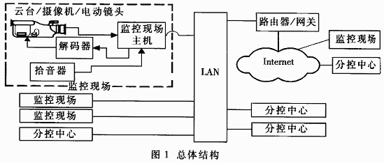
2 Design and implementation of network transmission module
WSA_FLAG_MULTIPOINT_D_LEAF);
figure 2
You can set socket properties through the setsocket function, such as address reuse, whether the buffer is received or sent.