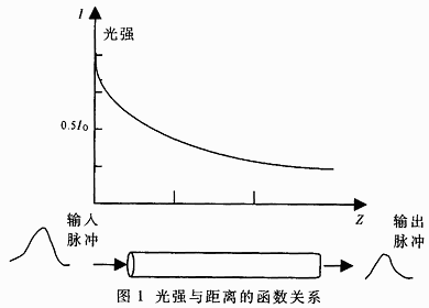
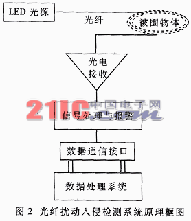
Keywords: optical fiber disturbance intrusion detection band-pass amplifier Optical fiber sensing includes two functions of perception and transmission of external signals (measured). The so-called perception (or sensitivity) refers to the measurement of the change of the optical parameter after the external signal changes the physical characteristic parameters (such as intensity, wavelength, frequency, phase and polarization state) of the light wave transmitted in the optical fiber according to its changing law. 1 Principle of disturbance 1.1 Fiber characteristics Optical fiber is a thin cylinder composed of quartz materials with different refractive indexes. The inner layer of the cylinder is called the core, and the outer layer is called the cladding. Light (or optical signals) are transmitted in the core. Suppose the refractive index of the core is n1 and the refractive index of the cladding is n2. In order to allow light to travel only in the core and not escape through the cladding, the condition of total reflection must be formed at the interface between the core and the cladding. That satisfies n1> n2. In addition to the refractive index parameters, the optical fiber has other parameters, such as relative refractive index, numerical aperture NA, attenuation, mode (single mode, multimode), etc. For this system, the attenuation parameter is more important. The optical pulse with a peak intensity (optical power) of I0 in the fiber is injected into the fiber core from the left end. When the light propagates along the fiber, its intensity decreases exponentially, namely: I (z) = I0e-αZ (1) Among them, I0-the initial light intensity entering the fiber core (Z = 0); Z——the longitudinal distance along the fiber; α——Light intensity attenuation coefficient. The attenuation of optical power in the fiber is shown in Figure 1. The definition of fiber attenuation rate is: the decibel loss of light intensity for each kilometer of light propagating in the fiber. which is: Attenuation rate = ï¼10lg (I / I0) db / km) (2) The attenuation rate of the optical fiber is only related to the attenuation coefficient, and there are many reasons for the optical attenuation, such as material absorption, bending loss and scattering loss. The optical fiber disturbance intrusion detection mainly uses the different intensity of different external disturbances to the optical fiber. Modulate the frequency to detect disturbances. 1.2 Perturbation loss The perturbation loss in the optical fiber refers to the loss caused by the geometrical non-uniformity of the optical fiber, which includes the non-uniformity caused by internal factors and external interference, such as the non-uniformity of the refractive index and diameter on the macrostructure, microbending, etc. According to the theory of optical fiber transmission, the loss caused by this non-uniformity appears either in the form of scattering or in the form of mode coupling. Mode coupling refers to the energy exchange or energy transfer between the conduction mode of the optical fiber, and between the conduction mode and the radiation mode. This means that the light passing through the fiber will be attenuated. In general, these losses should be reduced and avoided when manufacturing and using optical fibers, but fiber disturbance intrusion detection mainly uses the attenuation of these losses to detect the existence of intrusion, so it is important to study these losses, especially microbending losses. of. The microbending loss is caused by the mechanical inductive coupling between the modes. The conduction mode in the optical fiber is transformed into the cladding mode and disappears from the core. This loss increases when the spatial period of mechanical perturbation along the fiber coincides with the wavenumber difference of adjacent modes in the fiber. The approximate experimental relationship is as follows: Fiber microbending loss ∠(core radius / fiber radius) 2 · (2 â€‹â€‹ï¼ NA · A) 4 (3) Among them, N · A is the numerical aperture of the optical fiber. When light enters the end face of the fiber from air, only the light in the direction of a certain light cone can stay in the fiber core after entering the fiber, and the light incident from outside the light cone Even if light enters the fiber, it will escape from the cladding. The sine of the half angle of this light cone is called the numerical aperture of the fiber. 1.3 Characteristics of LED light source λ = hc / Eg≈1.24 / Eg (μm) (4) Where? H is the Planck constant and c is the speed of light. The line width of the LED is generally 5% of its center wavelength, because the selectivity of the gain will narrow the line width. Common materials used to manufacture LEDs are shown in Table 1. The LED output power at a wavelength of 850 nm is usually in the range of 1 to 10 mW. For devices with a wavelength less than 850 nm, the available power is significantly reduced. The output power and wavelength of all LEDs change with temperature. At 850 nm, the typical temperature coefficients of output power and wavelength are 0.5% C-1 and 0.3 nmC-1, respectively, so the thermal stability is for fiber disturbance intrusion detection Factors to consider. 2 Hardware technical solutions The functional block diagram of the optical fiber disturbance intrusion detection system is shown in Figure 2. The system mainly includes: carrier frequency signal source circuit, LED light source, PIN photoelectric detector, optical fiber, disturbance intrusion detection, alarm transmission interface circuit, etc. 2.1 Design of sensing circuit 2.2 Design and simulation of band-pass filter After the disturbance signal is identified by the amplification and band pass filter, the disturbance signal is detected, In the research of optical fiber disturbance intrusion detection technology, the mechanism of optical fiber disturbance signal was studied, the theoretical study of LED and optical fiber characteristics and perturbation loss, etc., and the use of Agilent's optoelectronic devices HFBR-1424 and HFBR-2416 And multi-mode optical fiber design of the optical fiber sensing system, at the same time the front-end carrier frequency signal source circuit and the subsequent disturbance signal amplification circuit are designed, the detection circuit is designed and simulated by the method of band pass filtering, and the successful implementation of the Disturbance signal detection. 38120 10Ah 3.2V Lithium Ion Battery Lithium Ion Battery Price,Dewalt Lithium Ion Battery,Hw38120L 10Ah Lifepo4 Battery,Hw38120S 10Ah Lifepo4 Battery Zhejiang Xinghai Energy Technology Co.,Ltd , https://www.headwayli-battery.com This "perception" is essentially the modulation of light waves propagating in the fiber by external signals. According to the change of physical characteristic parameters of light waves modulated by external signals, the modulation of light waves can be divided into five types: light intensity modulation, light frequency modulation, light wavelength modulation, and light phase and polarization modulation. The influence of external disturbances (such as vibration, bending, squeezing, etc.) on the luminous flux in the optical fiber belongs to the functional light emphasis system. The detection of microbending generally adopts the periodic microbending detection method. It is necessary to borrow a sensor board to manually bend the optical fiber periodically, so that the light intensity is modulated. It is generally used to detect small displacements and can be used as an industrial pressure sensor, which has high accuracy , The design is more complicated. The purpose of optical fiber disturbance intrusion detection is to detect intrusion, and does not require high precision. Because high precision is easy to generate false alarms, the above method cannot be used. This paper proposes a different range of disturbance modulation frequencies using different intrusion objects (such as people, wind, etc.), using general multimode fiber, and bandpass filters for bandpass amplification in subsequent circuits to filter out the modulation frequency of intrusion disturbance signals , An effective method of intrusion detection. According to the analysis of the intruding objects and the intruding frequency, the design and simulation of the bandpass filter circuit of 0.1 ~ 30Hz, effectively filter out the influence of power supply ripple and temperature drift, and design the disturbance detection system. In practical applications, the intrusion detection system is installed on the periphery of a certain area or on special objects, such as fences or objects to be detected, which can effectively detect unauthorized activities such as intrusion, tampering, and replacement.

Figure 4 Bandpass filter simulation circuit diagram
The optical characteristics of LED light source mainly include wavelength, line width, output power, fiber coupling and so on. The central emission wavelength λ of the LED depends on the energy gap Eg of the semiconductor material, and its formula is:
Table 1 List of commonly used materials for manufacturing LED Materials Emission wavelength / nm Light spectrum GaP 700 red GaAlAs 650 ~ 850 Red to near infrared GaAs 900 Near infrared InGaAs 1200 ~ 1700 Near infrared

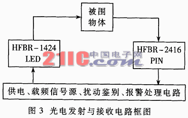
The purpose of the carrier frequency signal source circuit is to increase the transmission power of the LED, and at the same time to realize the detection of the slowly changing LED photocurrent at the receiving end. The photoelectric transmitting and receiving circuit is composed of three parts such as LED light source, optical fiber, and PIN photoelectric detector, and forms a sensing unit, as shown in Figure 3. The LED adopts the HFBR4000 series low-power and high-efficiency LED from the American company Agilent. Its model is HFBR-1424, the wavelength of the emitted light wave is 850nm, the bandwidth of 125MHz, the cut-off frequency is 35MHz, and the output optical power is 50-100W. The optical fiber transmission length is 4km, and the operating temperature range is -40 ° C to 85 ° C. It is suitable for coupling with optical fibers such as 50 / 125μm, 62.5 / 125μm, and 100 / 140μm. At present, PIN diodes are commonly used in optical fiber communication for light detection, and the optical signal is converted into a current signal. However, because the current signal is very weak, only pA level, it is difficult to effectively convert it to a volt level voltage for subsequent circuits to carry out the signal Processing and using; previously used expensive high-performance operational amplifiers to form the amplifier circuit, but the experimental results are not very ideal, and are easily affected by external electromagnetic interference; in order to overcome these shortcomings, the use of HFBR 2416 produced by the American Agilent company, it is the PIN A new optical plug-in device with integrated photodetector and preamplifier. The main features of HFBR2416 are as follows: (1) Integrate PIN photodetector with preamplifier, which can directly output a large voltage signal; (2) Only a small number of external components can form a high-performance optical receiving circuit, typical bandwidth Up to 125MHz; (3) Can be used in analog and digital optical communication systems, with good anti-interference performance; (4) Compatible with other products of the HFBR0400 series, in line with international industrial standards, good applicability; (5) Multiple packaging forms, small size , Light weight; (6) The price is cheap. Its specific technical parameters are shown in Table 2.
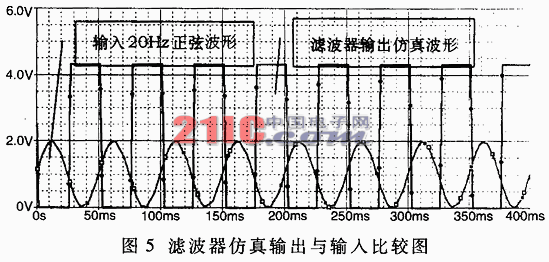
Table 2 HFBR2416 technical parameter table Parameter meets the Minimum value Maximum General value Unit Comment voltage Voc -0.5 6.0 V The output voltage Vsig -0.5 Vcc V Output impedance Zo 30 Ω f = 50MHz Responsiveness RP 5.3 9.6 7 mV / μs Wavelength 850, 50MH Rise / fall time Tr / tf 6.3 3.3 ns Rp = 100μW, peak Pulse width distortion PWD 2.5 0.4 ns Rp = 100μW, peak Bandpass BW 125 MHz  And generate an alarm. The most important of the above circuits is the band-pass filter. The modulated signal is changed from an electrical signal to an optical signal by LED. After the optical signal is transmitted through the optical fiber, it is amplified by the optical signal to the PIN signal and amplified. The amplifier outputs a pulse with a frequency of 100 kHz and an amplitude of 500 mV. Experiments show that the disturbance signal shows a reduction in the amplitude of the waveform on the output waveform, and the variation range is in the order of mV. The change in the luminous flux caused by the disturbance can be estimated by the amplification of the amplifier, which is about tens of μV. According to the characteristics of human actions, the movement frequency should be in the range of 0.1 ~ 30Hz. Based on the above considerations, a band-pass filter was designed to filter out the low frequencies below 0.1Hz, so that the photocurrent and the system's slowness The drift is omitted, and the signal higher than 30 Hz is filtered out, so that the carrier frequency and power supply ripple can be filtered out. Figure 4 is a simulation circuit diagram of the band-pass filter, and Figure 5 is a comparison diagram of the filter simulation output and input. It can be seen from Figure 5 that the design of the active band-pass filter can detect the simulated disturbance signal with a frequency of 20 Hz. In the actual circuit, the filter hardware circuit is designed according to the simulation circuit to realize the detection of the disturbance signal of a certain frequency. The filter output waveforms of single-time disturbance signal and continuous disturbance signal are shown in Figure 6 and Figure 7. When there is no disturbance signal, the filter has no output. When there is a disturbance signal of a certain frequency, the filter outputs a pulse signal. After the signal is amplified by shaping, it can drive the relay to generate an alarm, or be transmitted to the remote end for further processing through wireless transmission.
Abstract: Through a certain amount of light with a constant amplitude in the optical fiber, the intensity of the light in the optical fiber will change when the external disturbance is. Therefore, the detection of this change in light intensity can detect the intrusion of external disturbance. The detection of the functional light-emphasis system generally uses special optical fibers that are sensitive to certain physical characteristics to achieve the purpose of measurement, but the fiber structure is more complicated. The mechanism of fiber disturbance is discussed, and a general multi-mode fiber is used to detect the disturbance signal frequency of different intruding objects, and a band-pass filter circuit is used to realize the detection method. The bandpass amplifier technology is designed and simulated to realize the intrusion detection of disturbance signals.