Portable Monitor Holder For Laptop,Adjustable Portable Laptop Holder,Adjustable Ergonomic Portable Aluminum Laptop Holder,Foldable Portable Desktop Laptop Holder,etc.
Shenzhen Chengrong Technology Co.ltd is a high-quality enterprise specializing in metal stamping and CNC production for 12 years. The company mainly aims at the R&D, production and sales of Notebook Laptop Stands and Mobile Phone Stands. From the mold design and processing to machining and product surface oxidation, spraying treatment etc ,integration can fully meet the various processing needs of customers. Have a complete and scientific quality management system, strength and product quality are recognized and trusted by the industry, to meet changing economic and social needs .
Portable Monitor Holder For Laptop,Adjustable Portable Laptop Holder,Adjustable Ergonomic Portable Aluminum Laptop Holder,Foldable Portable Desktop Laptop Holder Shenzhen ChengRong Technology Co.,Ltd. , https://www.laptopstandsupplier.com
The rapid expansion of the wireless communication sector has sparked a significant surge in the demand for testing solutions across the industry. This includes comprehensive testing of the various radio frequency (RF) integrated circuits (ICs) and microwave monolithic integrated circuits (MMICs) that form the backbone of modern communication systems. These tests typically operate at extremely high frequencies, often reaching into the gigahertz range. This article delves into critical aspects of RF and microwave switching test systems, covering different switch types, specifications for RF switch cards, and design considerations that assist test engineers in boosting test efficiency while reducing costs.
While it might seem straightforward to transition signals between frequency points, achieving this with minimal signal loss presents unique challenges. Switch systems designed for low-frequency and DC signals must account for distinct parameters like contact potential, settling time, bias current, and isolation characteristics. Conversely, high-frequency signals require attention to parameters such as VSWR (voltage standing wave ratio), insertion loss, bandwidth, and channel isolation. Additionally, hardware elements like terminations, connector types, and relay types significantly impact these parameters.
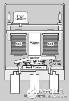
Switch types and construction play a crucial role in determining the operational frequency range of a switch. Relay capacitance, influenced by the relay's material and physical properties, often limits the frequency range. In RF and microwave switches exceeding 40 GHz, specialized contact architectures in electromechanical relays enhance performance. Figure 1 illustrates a common termination configuration where both switch terminations share a single connection. All signal connections are coaxial to maintain optimal signal integrity (SI). Here, the connector is an SMA female. For more intricate switch configurations, the common termination is individually terminated for each switch termination radially.
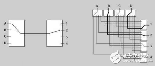
A variety of complex switching topologies are employed in RF switches. Matrix switches enable each input to connect to every output. Two types of matrices are commonly used in microwave switch architectures: blocking and non-blocking. Blocking matrices allow any input to connect to any output, preventing simultaneous connections to other inputs and outputs. This cost-effective approach is ideal for applications requiring single-signal frequency switching, offering superior signal integrity by minimizing relay paths and avoiding phase delay issues. Non-blocking matrices, while more expensive due to their increased complexity and higher component count, permit simultaneous multiple-path connections, providing greater flexibility.
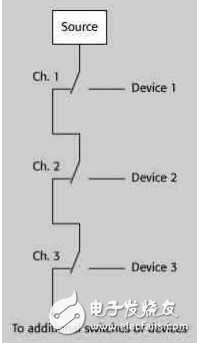
Stacked switch architectures serve as alternatives to multi-position switches, using multiple relays to connect one input to several outputs. The path length, which affects phase delay, depends on the number of relays traversed by the signal.
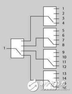
Tree architectures offer another alternative to stacked switch designs. Although requiring more relays for equivalent systems, tree technology provides better isolation between selected and unused paths, reducing crosstalk. Key benefits include unterminated stubs and consistent channel characteristics. However, the presence of multiple relays on selected paths results in higher losses and concerns over signal integrity.
RF switch card architecture plays a pivotal role in ensuring signal integrity within test instruments. Parameters such as crosstalk, insertion loss, VSWR, bandwidth, and isolation must be carefully considered.
Designing an RF switching system involves additional considerations. Impedance matching ensures seamless signal transmission between the test equipment and the device under test (DUT). All impedances in the system—source output, switch, cable, and DUT—must align, typically at 50 or 75 ohms. Proper matching guarantees overall system integrity.
Input VSWR and signal path VSWR influence measurement accuracy:
Mismatch Uncertainty (dB) = 20 x log(1 ± Γsig path × Γinst)
Where Γ = (VSWR-1)/(VSWR+1).
For instance, if the signal path output and instrument input exhibit a VSWR of 1.3:1, mismatch uncertainty would be approximately ±0.15 dB.
Termination is critical at high frequencies to prevent electromagnetic reflections. An unterminated switch increases VSWR in the off-state. A 50-ohm termination resistor is typically necessary to match the connected and disconnected states.
Power transfer is another vital aspect, ensuring efficient RF power transmission from the instrument to the DUT. Amplifiers or attenuators may be needed to compensate for insertion loss, depending on the application requirements.
Signal filters are beneficial in certain scenarios, such as when noise interferes with the transmitted signal or when the original frequency is unsuitable for the DUT test frequency. Filters can modify signal bandwidth or eliminate undesired frequencies.
Phase distortion arises as test systems grow larger, causing signals from the same source to reach the DUT via different paths, leading to erroneous measurements. Minimizing phase distortion requires equalizing signal path lengths.
In conclusion, understanding and addressing the diverse design parameters in RF/microwave switching systems is essential for maintaining signal and system integrity. By carefully considering these factors, engineers can optimize test setups, reduce costs, and enhance overall system reliability.