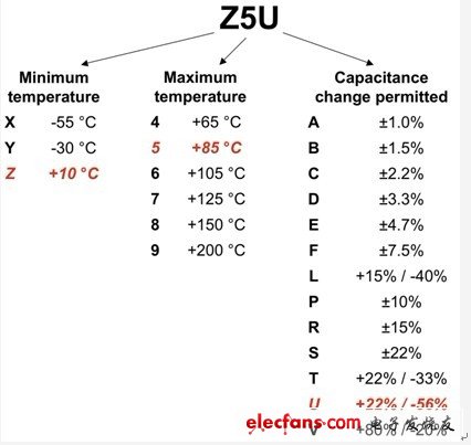
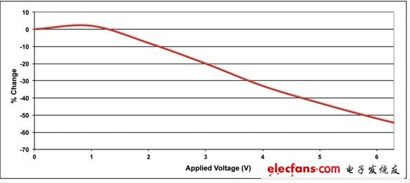
Multilayer ceramic (MLC) capacitors have become extremely popular in power electronics due to their small size, low equivalent series resistance (ESR), low cost, high reliability, and high ripple current capability. In general, they are used in electrolytic capacitors leiu to enhance system performance. MLC capacitors have the advantage of high relative dielectric constant materials (2000-3000) compared to electrolytes with a relative dielectric constant of 10 when using electrolytic capacitor aluminum oxide insulation. This difference is important because the capacitance is directly related to the dielectric constant. At the positive end of the electrolyte, the thickness of the alumina separating the plates is set to be smaller than that of the ceramic material, resulting in a higher capacitance density. The ceramic capacitor has a dielectric constant that is unstable when the temperature and DC bias change, so we need to understand this characteristic during the design process. High dielectric constant ceramic capacitors are classified into two categories. Figure 1 shows how to classify them in a 3-digit description, such as Z5U, X5R, and X7R. For example, Z5U capacitors are rated for temperatures from +10 to +85o C and range from +22/–56%. Re-stabilized dielectrics also have a certain range of temperature capacitance variations. Figure 1: Class 2 dielectrics are classified using 3 digits. Pay attention to observe its tolerance! The situation gets even worse when we study the bias capacitance dependence. Figure 2 shows the bias dependence of a 22 uF, 6.3 volt, X5S capacitor. We often use it as an output capacitor for a 3.3 volt point-of-load (POL) regulator. A 3.3% reduction in capacitance at 3.3 volts results in an increase in output ripple, which has a large impact on the control loop bandwidth. If you have used this capacitor at a 5 volt output, the capacitance is reduced by as much as 60% between temperature and bias, and an unstable power supply can occur due to the 2:1 loop bandwidth increase. Many ceramic capacitor manufacturers have not elaborated on this issue. Figure 2: Pay attention to the bias change of the capacitor A second potential drawback of ceramic capacitors is that they have relatively small capacitance and low ESR. This can cause problems in the frequency and time domains. If they are used as input filter capacitors for a power supply, they easily resonate with the input interconnect inductors, forming a "Power Design Tip 3" (http://www.TI.com.cn/general /cn/docs/gencontent.tsp?contenTId=53863 ) and Power Supply Tip 4 (http://www.TI.com.cn/general/cn/docs/gencontent.tsp?contenTId=53864 ) Discuss the oscillator. To find out if there are potential problems, estimate the parasitic interconnect inductance to 15 nH per inch and compare the filtered output impedance to the power input resistance as described in the two articles. The second potential problem exists in the time domain, and we can see them in systems such as Power over Ethernet (POE). In these systems, the power supply is connected to the load through a large interconnect inductor. The load is turned on with a switch and a ceramic capacitor can be used to build the bypass. This bypass capacitor and interconnect inductor can form a high Q resonant circuit. Since the load voltage ringing can be as high as twice the supply voltage, turning off the switch under load creates an overvoltage condition. This can cause unexpected circuit failures. For example, in a POE, the load component can be rated for up to twice the rated voltage of the power supply. The third potential defect is due to the fact that the ceramic capacitor is piezoelectric. That is, as the capacitor voltage changes, its physical size changes, producing audible noise. For example, when we use this capacitor as an output filter capacitor (there is a large load transient current), or in a "green" power supply, it enters burst mode under light load conditions. The workaround for this problem is as follows: · Switch to ceramic materials with lower dielectric constants, such as COG. · Use different dielectrics, such as films. · Uses leaded and surface mount technology (SMT) components to closely conform to printed circuit boards (PWB). · Reduce board stress with smaller form factor devices. · Use thicker components to reduce applied voltage stress and physical deformation. Another problem with SMT ceramic capacitors is that their soft solder joints tend to crack when the PWB is bent due to the thermal expansion coefficient (TCE) mismatch between the capacitor and the PWB. You can take some precautions to reduce this problem: · The package size is limited to 1210. • Keep capacitors away from areas of high curvature, such as corner areas. • Place the capacitor in the short direction toward the board. • Keep board mounting points away from corners. · Pay attention to possible board bending during all assembly procedures. In short, if you pay attention to some of its shortcomings, multilayer ceramic capacitors have the advantages of low cost, high reliability, long life and small size compared to electrolytic capacitors. They have a very wide range of capacitance tolerances, so you need to evaluate performance over temperature and bias variations. They are all piezoelectric, which means they produce audible noise in systems with pulsed currents. Finally, they are prone to rupture, so we must take precautions to reduce this problem. All of these problems have corresponding solutions. Therefore, MLC capacitors will continue to become more and more popular. Next time, we will continue to discuss the choice of capacitors for switching power supplies, so stay tuned. Replacement for traditional Neon lighting of Structure outline such as Roofs, Windows, Doors, Storefronts and Carports
*Low power consumption, Super-bright led light running with low temperature
*All the light spread and completely smooth, luminous very even
*Flexible, Slim, compact and flexible PCB strip. Applicable for bendable or angled patterns, or in continuous rows
*Cuttable and linkable. It can be cut in every 1.64ft/0.5m along the cutting marks, without damaging the rest strips
*LED Type: High Quality 5050 SMD LED, high intensity and reliability, Long lifespan up to 50,000+ hours Led Neon Lights,Led Neon Rope Light,Neon String Lights,Led Neon Flex Light XINGYONG XMAS OPTICAL (DONGGUAN ) CO., LTD , https://www.xingyongled.com