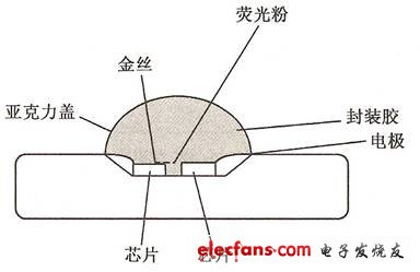
In the daily life, with the rapid development of LED, we have more and more opportunities to access LED. But in addition to knowing that LEDs have high brightness, low power consumption, long life, etc. Have we ever explored the production process of an LED lamp? Below we introduce the LED manufacturing process. 1. LED chip inspection Microscopic examination: whether there is mechanical damage on the surface of the material and whether the size and electrode size of the lockhill chip and the electrode size meet the process requirements. 2.LED expansion Since the LED chip is still arranged with a small close spacing (about 0.1 mm) after dicing, it is not conducive to the operation of the post process. The film of the bonded chip is expanded by a spreader to stretch the pitch of the LED chip to about 0.6 mm. It can also be manually expanded, but it is easy to cause problems such as chip falling waste. 3.LED dispensing Place silver glue or insulating glue on the corresponding position of the LED bracket. For GaAs, SiC conductive substrates, red, yellow, and yellow-green chips with back electrodes are made of silver paste. For blue and green LED chips of sapphire insulated substrates, insulating glue is used to fix the chips. The difficulty of the process lies in the control of the amount of glue, and there are detailed technical requirements in the height of the glue and the position of the glue. Since silver glue and insulating glue have strict requirements in storage and use, the wake-up, stirring and use time of silver glue are all matters that must be paid attention to in the process. 4.LED preparation glue In contrast to dispensing, the glue is applied to the back electrode of the LED with a glue machine, and then the LED with silver glue on the back is mounted on the LED holder. The efficiency of the preparation glue is much higher than that of the dispensing, but not all products are suitable for the preparation process. 5.LED hand-piercing The expanded LED chip (with or without glue) is placed on the jig of the lancet table, and the LED holder is placed under the clamp, and the LED chips are punctured one by one under the microscope with a needle. Hand-made thorns have an advantage over automatic loading, making it easy to replace different chips at any time, for products that require multiple chips. 6.LED automatic mounting The automatic loading is actually a combination of two steps of glue (dispensing) and mounting the chip. First, put silver glue (insulating glue) on the LED bracket, then use the vacuum nozzle to suck the LED chip to the moving position, and then place it in the The corresponding bracket position. In the process of automatic loading, the equipment should be familiar with the operation and programming of the equipment, and at the same time adjust the glue and installation accuracy of the equipment. In the selection of the nozzle, the bakelite nozzle should be used as much as possible to prevent damage to the surface of the LED chip. In particular, the blue and green chips must be made of bakelite. Because the steel nozzle will scratch the current diffusion layer on the surface of the chip. 7.LED sintering The purpose of sintering is to cure the silver paste, and the sintering requires monitoring of the temperature to prevent batch defects. The temperature at which the silver paste is sintered is generally controlled at 150 ° C and the sintering time is 2 hours. According to the actual situation, it can be adjusted to 170 ° C for 1 hour. The insulating glue is generally 150 ° C for 1 hour. The silver-glued sintering oven must be opened and replaced with a sintered product within 2 hours (or 1 hour) according to the process requirements, and should not be opened at will. Sintering ovens must not be used for other purposes to prevent contamination. 8.LED pressure welding The purpose of the pressure welding is to lead the electrode to the LED chip to complete the connection of the inner and outer leads of the product. There are two kinds of LED pressure welding processes: gold wire ball bonding and aluminum wire pressure welding. The process of aluminum wire bonding is to first press the first point on the electrode of the LED chip, then pull the aluminum wire over the corresponding bracket, and press the second point to tear the aluminum wire. The gold wire ball bonding process burns the ball before the first point, and the rest of the process is similar. Pressure welding is a key link in LED packaging technology. The main requirements of the process are the pressure welding of gold wire (aluminum wire) arch shape, solder joint shape, and tensile force. 9.LED sealant LED packaging is mainly a little glued, potted, molded. Basically, the difficulty of process control is bubbles, lack of materials, and black spots. The design is mainly for the selection of materials, and the combination of good epoxy and brackets is selected. (General LEDs cannot pass the air tightness test) LED dispensing TOP-LED and Side-LED are suitable for dispensing. Manual dispensing requires a high level of operation (especially white LEDs). The main difficulty is the control of the amount of dispensing, as the epoxy thickens during use. The dispensing of white LEDs also has the problem of phosphor precipitation leading to chromatic aberration of light. LED potting package Lamp-LED package is in the form of potting. The potting process is to first inject liquid epoxy into the LED molding cavity, then insert the pressure-bonded LED bracket into the oven to cure the epoxy, and then remove the LED from the cavity to form. The LED molded package puts the pressure-welded LED bracket into the mold, molds the upper and lower molds with a hydraulic machine and vacuums them, and puts the solid epoxy into the inlet of the injection line to press the hydraulic ejector into the mold rubber path. The epoxy enters each LED forming slot along the glue path and cures. 10. LED curing and post curing Curing refers to the curing of the encapsulating epoxy, which is typically cured at 135 ° C for 1 hour. The molded package is typically at 150 ° C for 4 minutes. Post-cure is to allow the epoxy to fully cure while thermally aging the LED. Post-cure is important to increase the bond strength of the epoxy to the support (PCB). The general conditions are 120 ° C for 4 hours. 11.LED cutting and dicing Since the LEDs are connected together in a production process (not a single one), the Lamp packaged LED uses a rib to cut the ribs of the LED holder. SMD-LED is on a PCB Board and requires a dicing machine to complete the separation. 12. LED test Test the photoelectric parameters of the LED, verify the external dimensions, and sort the LED products according to customer requirements.
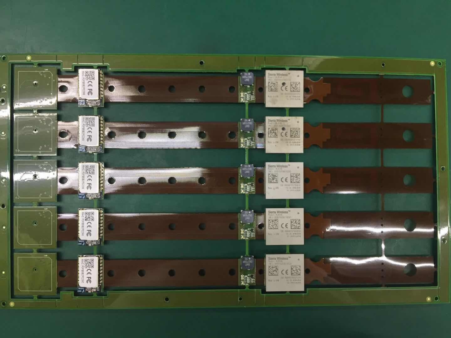
Surface-mount technology (SMT) is a method for producing electronic circuits in which the components are mounted or placed directly onto the surface of printed circuit boards (PCBs). An electronic device so made is called a surface-mount device (SMD). In industry, it has largely replaced the through-hole technology construction method of fitting components with wire leads into holes in the Circuit Board. Both technologies can be used on the same board, with the through-hole technology used for components not suitable for surface mounting such as large transformers and heat-sinked power semiconductors.
Surface Mount Technology,Surface Mount,Surface Mount Assembly,Surface Mounting Technology Orilind Limited Company , https://www.orilind.com
By employing SMT, the production process speeds up, but the risk of defects also increase due to the components miniaturization and denser packing of boards. In those conditions, detection of failures has become critical for any SMT manufacturing process.[1]
An SMT component is usually smaller than its through-hole counterpart because it has either smaller leads or no leads at all. It may have short pins or leads of various styles, flat contacts, a matrix of solder balls (BGAs), or terminations on the body of the component.
