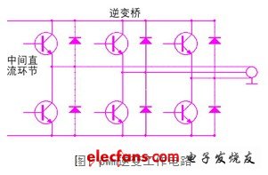
As a driving power source of a high-power module, a main circuit such as a switching circuit, an amplifying circuit, and an inverter circuit may interfere with an electromagnetic environment. Therefore, when designing the drive module, the electromagnetic compatibility problem must be considered to avoid the interference of the drive unit to the outside world. 1 Basic principles of electromagnetic compatibility Electromagnetic compatibility means that electrical and electronic equipment can perform the coexistence state of their respective functions in a common electromagnetic environment, and all of them can work normally without interference and reach a compatible state. Electromagnetic interference can be represented by time domain and frequency domain. Most of the interference signals are time-varying. For discussion and analysis, frequency domain analysis methods are suitable. Typical signal representations are sinusoidal, non-sinusoidal, periodic, aperiodic, and pulsed, all of which are conducted through space radiation and through wires. In the project, the non-periodic signal and the pulse signal are used more frequently, and the interference signal is represented by f(t), and the non-periodic signal Fourier integral is It is also possible to perform a Fourier transform on the pulse signal to obtain a spectrogram. Electromagnetic interference is transmitted by electric and magnetic fields. Therefore, the basic unit can also be expressed by the unit of electric field and magnetic field. Decibel is commonly used in engineering to measure electromagnetic interference, namely db. 2 Electromagnetic compatibility implementation When the drive unit housing is selected, the material with good shielding effect should be considered in combination with cost performance. In the design of the drive unit, the intermediate point clamp type pwm inverter circuit is used as the main working circuit. When the power device is switched, the circuit generates harmonic current, and the high frequency component radiates into space. Pwm inverter working circuit is shown in Figure 1. For this reason, electromagnetic compatibility should be fully considered in all aspects of component selection, circuit board design and interface design, so that the drive module works in a normal state without affecting other devices.
880nm LED can be packaged as SMD LED or through-hole LED.
880nm LED 880nm LED, 880nm IR LED, High Power 880nm LED,890nm LED,890nm Infrared LED Shenzhen Best LED Opto-electronic Co.,Ltd , https://www.bestsmd.com
We can customize the shape, the lighting angle, the number of emitting source, the flat pin LED and braided LED. Such as: infrared 5mm 880nm LED with 5 degree, infrared 5mm 880nm LED with 20 degree, infrared 5mm 880nm LED with 30 degree, infrared 5mm 880nm LED with 45 degree, infrared 5mm 880nm LED with 60 degree, infrared 5mm 880nm with 90 degree, infrared 5mm 880nm LED with 120 degree. Infrared 3mm 880nm LED with 3 degree, infrared 3mm 880nm LED with 20 degree, infrared 3mm 880nm LED with 30 degree, infrared 3mm 880nm LED with 45 degree, infrared 3mm 880nm LED with 60 degree, infrared 3mm 880nm with 90 degree, infrared 3mm 880nm LED with 120 degree ect.
There are many other shapes or color of lens for your choose. Customized infrared LED are available.
For the SMD LED 880nm LED,
We can supply dual-chip infrared LED, three-chip infrared LED, multi-chip infrared LED, high voltage LED, flashing infrared LED and variety of size SMD LED. For instance: 3528 SMD infrared 880nm LED, 2835 SMD infrared 880nm LED, 3014 SMD infrared 880nm LED, 1206 SMD infrared 880nm LED, 3020 SMD infrared 880nm LED.
There are also have many other shapes to choose, like the 5050 SMD infrared LED, the 5730 SMD infrared LED ect. You can choose any one of them for your requirement.
880nm led is a infrared LED( IR LED ). Common infrared LEDs are like: 860nm IR LED, 870nm IR LED, 875nm IR LED, 880nm IR LED, 890nm IR LED, 900nm IR LED and so on.