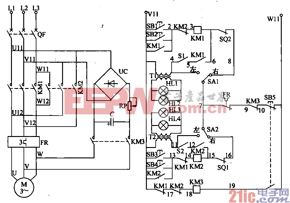
The electric valve control circuit is composed of three key parts: the main line, the control line, and the energy consumption braking line. The main line includes the power switch QF, the main contacts of the three-phase AC contactors KM1 and KM2, the components of the thermal relay FR, and the three-phase AC motor. The control circuit includes control buttons SB1-SB5, the lines BH of AC contactors KM1-KM3 and their auxiliary contacts, power transformers T1 and T2, signal indicators HL1-HL3, flash switches S1 and S2, state selection switches SA1 and SA2, and position switches SQ1 and SQ2, among others. The energy consumption circuit includes a bridge rectifier UC, a current-limiting potentiometer RP, a storage capacitor C, and the main contact of the AC contactor KM3. The electric valve motor control circuit is illustrated in Figure 4-35. In the hot standby state, the main line can be manually controlled or automatically controlled depending on the positions of the SA1 and SA2 switches. When SA1 (or SA2) is set to the left, the coil of KM1 (or KM2) is disconnected. While in operation, when SA1 (or SA2) is set to the right, the coil of KM1 (or KM2) is activated. When SA1 (or SA2) is on the left, the signal indicators light up, allowing operators or maintenance personnel to verify if the control circuit is powered. When SA1 (or SA2) is on the right, the signal indicators remain off until the valve motor starts, at which point the indicators HL1, HL2 (HL3, HLA) begin to flash. By closing the power switch QF, setting the selector switch SA1 to the right, and pressing SB1 (or SB2), the current flows through V11-SB1 (or SB2)-KM2 contact (2-3)-KM1 coil-SQ2-SA1-FR contact (7-9)-KM3 contact (9-10)-SB5-V11. The KM1 coil becomes energized, rotating the valve motor and opening the valve. Once the KM1 contact (5-6) is closed, the flash switch S1 activates, with the red light HL1 and green light HL2 flashing as indicators. When the valve reaches the limit position, SQ2 disconnects, de-energizing the KM1 coil, resetting its main contact, cutting off the power supply to the valve motor, and stopping the motor. Setting the selector switch SA2 to the right and pressing SB3 (or SB4) results in the current flowing through V11-SB3 (or SB4)-KM1 contact (13-14)-KM2 coil-SQ1-SA2-FR contact (7-9)-KM3 contact (9-10)-SB5-V11. The KM2 coil becomes energized, rotating the chain motor and closing the valve. After the KM2 contact (12-15) closes, the flash switch S2 operates, flashing the red light HL3 and the green light HL4. When the valve reaches the closed limit position, the position switch SQ1 disconnects, de-energizing the KM2 coil, resetting its main contact, cutting off the power to the motor, and stopping the valve. During the valve-opening process, pressing the stop button SB5 upon encountering an obstacle disconnects the breaking contact, de-energizing the KM1 or KM2 coil and stopping the motor. Simultaneously, the moving contact (19-21) of SB5 closes, energizing the KM3 coil. Its contact (9-10) disconnects, preventing the KM1 or KM2 coils from malfunctioning, while the main contact of KM3 closes. This allows the bridge rectifier output and the stored energy in the capacitor to generate a braking torque, causing the motor to stop instantly. This ensures precise stopping of the valve at the desired position. In Figure 4-35, the potentiometer RP serves as a current-limiting device, and the braking current can be adjusted by varying RP. Typically, the braking current is around 4.5A. In Figure 4-35, the electrolytic capacitor should be selected based on the valve's power. For motors with less than 2kW power, capacitors of 100-200μF can be used. For motors between 2kW and 5.5kW, capacitors of 400μF or higher can be used. The capacitor's voltage rating should exceed 600V. Digital Multimeter ,Bench Type Digital Multimeter,Meco Multimeter,Hioki Multimeter YINTE TOOLS (NINGBO) CO., LTD , https://www.yinte-tools.com