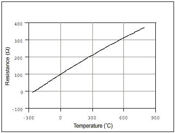
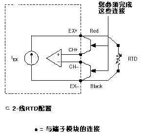
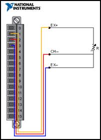
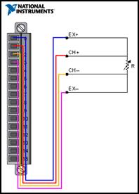
Based on PC data acquisition, measurement is performed through a combination of modular hardware, application software, and a computer. Although data acquisition systems have different definitions based on different application requirements, the purpose of each system to collect, analyze, and display information is the same. The data acquisition system integrates signals, sensors, actuators, signal conditioning, data acquisition equipment, and application software. RTD Overview <br> The typical resistance of a platinum resistance temperature sensor (RTD) at 0 °C is 100Ω. It consists of a platinum metal film superimposed on top of a plastic film. Its impedance changes with temperature, and usually it can measure temperatures up to 850 °C. The current flowing through the RTD creates a voltage difference across the RTD. By measuring this voltage difference, you can determine its impedance and determine its temperature. The relationship between impedance and temperature is approximately linear. RTD basic knowledge RTD is based on the principle of pure metal electronic impedance change and has the characteristic that impedance changes linearly with temperature. Typical elements used in RTDs include nickel (Ni) and copper (Cu), and platinum (Pt) is by far the most commonly used metal due to its wide temperature range, accuracy, and temperature. The RTD is constructed using one of two different manufacturing configurations. Winding RTDs are constructed by winding thin wires into a coil. A more common configuration is the use of a thin-film structure consisting of a very thin metal layer overlying a plastic or ceramic sub-layer. This thin film component is less expensive and more widely available because it can use higher platinum metal for higher nominal impedance. To protect the RTD, the RTD unit and the wires connected to it are enclosed in a metal sheath. With its stability RTD has been widely used, RTD has demonstrated the linearity of the relative signal temperature that no other electronic temperature sensor can match. However, due to the complex manufacturing process and the use of precious metal platinum, it is also generally more expensive than its alternatives. The RTD also has the characteristics of slow response and low sensitivity, and, due to the need for current excitation, it is prone to self-heating. RTDs are usually classified according to their nominal impedance at 0 °C. For platinum thin-film RTDs, typical nominal impedances include 100 Ω and 1000 Ω. The relationship between impedance and temperature is approximately linear and follows the following equation: When the temperature is below 0 °C, RT = R0 [ 1 + aT + bT2 + cT3 (T - 100) ] (Equation 1) When the temperature is higher than 0 °C, RT = R0 [ 1 + aT + bT2 ] Among them, RT is the impedance when the temperature is T, R0 is the nominal impedance, a, b and c are the proportional constants used by RTD respectively. The impedance-temperature curve for a 100 W platinum RTD (commonly referred to as Pt100) is shown in Figure 1. Figure 1. Impedance-temperature curve of a 100 Ω platinum RTD, where a = 0.00385 Although this relationship appears relatively linear, curve fitting is often the most accurate way to make accurate RTD measurements. Temperature measurement using RTD All RTDs usually use red and black or red and white wire color combinations. The red wire is the excitation wire, and the black wire or white wire is the ground wire. If you are not sure which wire is connected to which side of the impedance section, you can use a digital multimeter (DMM) to measure the impedance between the leads. If the impedance is close to 0 ?, these leads are connected to the same node. If the impedance is similar to the nominal measured impedance (100Ω is a common RTD nominal measurement impedance), the wires you measure are located at the opposite ends of the impedance section, respectively. In addition, consult the technical specifications of the RTD to determine the level of incentive for that particular device. Most instruments provide similar pin configurations for RTD measurements. The RTD is a passive measurement device, so you must provide it with excitation current and then read the voltage across its terminals. In turn, you can use a simple algorithm to easily convert the read voltage values ​​to temperature values. In order to avoid self-heating caused by the current flowing through the RTD, the excitation current should be minimized as much as possible. There are essentially three different ways to use RTD to measure temperature. 2-wire-RTD signal connection Connect the red lead of the RTD to the positive terminal of the excitation source. Use a jumper to connect the positive pin of the excitation source to the positive channel of the data acquisition device. Connect the black (or white) lead of the RTD to the negative terminal of the excitation source. Use a jumper to connect the negative pin of the excitation source to the negative channel of the data acquisition device. Figure 2. 2-wire RTD measurement In the 2-wire method, the two wires that apply the excitation current to the RTD are the same as the two wires used to measure the RTD voltage. The easiest way to obtain a temperature reading using an RTD is to use the 2-wire method; however, the disadvantage of this method is that the lead impedance of the wire is high, then the measured voltage Vo will be significantly higher than that carried by the RTD itself. Voltage. The NI 9217 does not support 2-wire measurement configurations. 3-wire-RTD signal connection Connect the red lead of the RTD to the positive terminal of the excitation source. Use a jumper to connect the positive pin of the excitation source to the positive channel of the data acquisition device. One of the black (or white) leads of the RTD is connected to the negative and negative channels of the excitation source, respectively. Figure 3 describes the external connections required for the measurement. Figure 3. 3-wire RTD measurement 4-wire-RTD signal connection To connect the RTD, simply connect each red lead on the positive side of its impedance section to the positive side of the excitation source and the positive channel of the data acquisition device. Each black (or white) lead located on the negative side of its impedance portion is connected to the negative polarity of the excitation source and the data acquisition device, respectively. Two additional leads from the 2-wire RTD increase the accuracy that can be achieved. Figure 4 describes the external connections required for this measurement. Figure 4. - Line RTD Measurement The advantage of the 4-wire method is that it is not affected by the impedance of the wire because these wires are located in the high-impedance path to the voltage measuring device. Therefore, you can obtain a much more accurate measurement of the RTD load voltage. RTD noise considerations The typical value of the output signal of the RTD is in the millivolt range and is therefore highly susceptible to noise interference. Low pass filters are often used in RTD data acquisition systems to effectively filter out high frequency noise in RTD measurements. For example, a low-pass filter is useful for filtering out 60 Hz power line noise that is common in most lab and factory environments. You can also significantly improve the noise performance of your system by amplifying the RTD voltage near the source to handle low voltage levels. Since the voltage level of the RTD output is very low, you should choose the appropriate gain to optimize the analog-to-digital converter (ADC) input limits. Check Your Measurement Results: NI LabVIEW Once the sensor is connected to the measurement instrument, you can use LabVIEW graphical programming software to visualize the data and analyze it as needed. Figure 5. LabVIEW RTD Measurement Excerpt from: NI "General Measurement Guide"
ZhenHuan`s line of Li-Ion Battery Charger range in output power from 6 W to 100 W features high energy efficiency and reliability, with quick charging function for 18650 batteries and li-ion batteries, etc. Our ac to dc power charger adopts constant voltage and constant current mode and accepts wall plug-in and desktop versions, all available with 2 colors LED indicator for charging status(Green and Red light). ZhenHuan`s power charger adapters solutions also includes class I and class II installations, equipped with three standard AC inlet options and different kinds of AC plugs.
Lithium Ion Battery Charger,Universal Laptop Charger,18650 Battery Charger,Li-Ion Battery Charger,UL Battery Charger,12V Battery Charger Shenzhenshi Zhenhuan Electronic Co Ltd , https://www.szzhpower.com