Multi Device Cables,Multi Usb Port Charger,Multi Usb C Charger,Multi Usb Cord UCOAX , https://www.ucoax.com
Measuring the current flowing through a sense resistor might seem straightforward—amplify the voltage and read it with an ADC. But what happens when the voltage at the sense resistor differs significantly from the system’s ground? The challenge intensifies if the common-mode voltage fluctuates rapidly or moves far from the system's ground. A traditional solution involves addressing this issue either in the analog or digital domains. However, there’s an innovative alternative—wireless.
Analog current sense ICs offer compact solutions, but their ability to handle voltage differences is constrained by semiconductor processes. Devices capable of handling voltages exceeding 100V are rare. These circuits struggle to measure accurately when the sense resistor’s common-mode voltage shifts unpredictably or varies widely. Digital isolation techniques, whether magnetic or optical, provide high precision and can withstand thousands of volts, but they tend to be bulkier and require an isolated power supply. Sometimes, this supply can be integrated within the isolator, but if the sense resistor is physically distant from the main system, long cables or wires might still be necessary.
The wireless current sensing circuit overcomes many of these limitations. By allowing the entire circuit to float with the sense resistor’s common-mode voltage and transmitting the measured data wirelessly, the voltage limit becomes irrelevant. The sense resistor can be positioned virtually anywhere without needing lengthy cable runs. If the circuit consumes minimal power, a separate power supply might not even be necessary—a small battery could keep it running for years.
### Design Overview
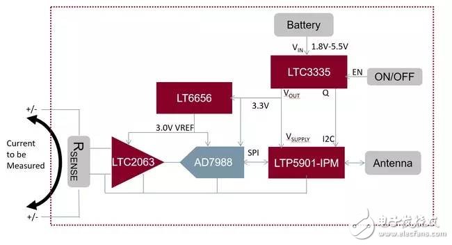
Figure 1 illustrates the design’s block diagram. The current sensing circuit employs the LTC2063, an ultra-low-power chopper-stabilized operational amplifier, to amplify the voltage drop across the sense resistor. The AD7988, a micropower SAR ADC, digitizes the amplified signal and communicates the result via the SPI interface. The LTP5901-IPM combines both a radio module and networking firmware that enables automatic formation of an IP mesh network.
Additionally, the LTP5901-IPM houses a microprocessor to read the ADC’s SPI port and manage communication. The LTC3335 is a low-power DC/DC converter that steps down the battery voltage to a stable output. It also includes a coulomb counter to monitor the charge drawn from the battery.
### Signal Chain
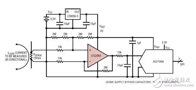
The LTC2063, an ultra-low-power chopper-stabilized op-amp, serves as the heart of the signal chain. With a maximum supply current of just 2µA, it’s perfect for battery-powered systems. Its offset voltage remains below 10µV, ensuring precise measurements of minuscule voltage drops. In Figure 2, the LTC2063 is configured to amplify the voltage across a 10mΩ sense resistor, shifting it to a level compatible with the ADC. By selecting the appropriate gain, the ±10mV full-scale input (corresponding to ±1A current) maps neatly to the ADC’s full-scale range, centered around 1.5V. This amplified signal feeds into the 16-bit AD7988 ADC. Known for its low standby current and excellent DC accuracy, the AD7988 automatically powers down between conversions, consuming as little as 10µA at 1ksps sampling rates. The LT6656 provides bias amplification, level-shifting resistors, and a stable reference input for the ADC. Consuming less than 1µA, the LT6656 can deliver precise 3V outputs even under varying system supplies.
Three primary sources of offset error contribute to approximately 0.5% error relative to the ±10mV full-scale input. These include the offset voltages of the LTC2063 and AD7988, as well as resistor mismatches in the level-shifting stage. A single-point calibration can largely eliminate this offset. Gain errors are usually dominated by the inaccuracies of the sense resistor, which often exceed the 0.05%, 10ppm/°C specifications of the LT6656 reference.
### Power Management
The LTC3335, a nanoscale power buck-boost converter with integrated coulomb counter, generates a regulated 3.3V output from inputs ranging from 1.8V to 5.5V. This versatility allows the circuit to operate from dual alkaline cells. For wireless applications operating intermittently, the load current ranges from 1µA in sleep mode to 20mA during active radio operation. The LTC3335’s no-load static power consumption is a mere 680nA, keeping the overall circuit power consumption exceptionally low during inactive periods. Moreover, it can supply up to 50mA, easily powering the circuit during radio transmission and reception.
The LTC3335’s integrated coulomb counter is particularly advantageous. It tracks the total charge removed from the battery, providing this data via the I²C interface to help predict when a replacement is needed.
### Wireless Networking
The LTP5901-IPM is a comprehensive radio module combining a transceiver, embedded microprocessor, and SmartMesh IP networking software. It fulfills two critical roles in this design: managing wireless networking and acting as a management microprocessor. When multiple SmartMesh IP nodes are powered on near the network manager, they automatically recognize each other and establish a wireless mesh network. The entire network synchronizes its timing, ensuring each radio powers up for only brief, specific intervals. Consequently, each node not only serves as a sensor source but also relays data from other nodes to the manager, creating a highly reliable, low-power grid with multiple redundant paths.
The LTP5901-IPM includes an ARM Cortex-M3 microprocessor core executing the networking software. Users can also upload custom application firmware to execute task-specific logic. In this case, the microprocessor within the LTP5901-IPM reads the SPI port of the current-measurement ADC (AD7988) and the I²C port of the coulomb counter (LTC3335). It can also put the chopper op-amp (LTC2063) into shutdown mode, reducing its power consumption from 2µA to 200nA. This significant power-saving feature proves invaluable in scenarios where measurements occur infrequently.
### Total Power Consumption
The total power consumption of the complete application circuit hinges on several factors, such as the frequency of signal-chain readings and the node’s role in the network. For a node reporting once per second, the measurement circuit typically consumes less than 5µA, while the radio consumes about 40µA. A small battery can sustain this setup for years.
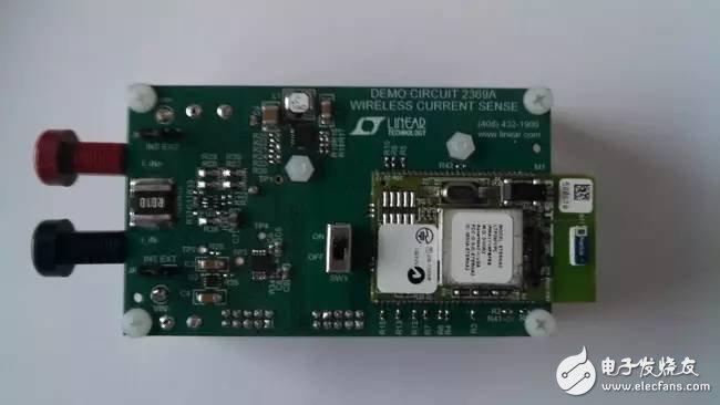
Linear Technology and Analog Devices’ combined portfolio of signal chains, power management, and wireless networking products enable the creation of true wireless current-sensing circuits. Figure 3 showcases an implementation example. The LTC2063, a novel ultra-low-power chopper op-amp, precisely measures minute voltage drops across the sense resistor. The entire circuit, including the micropower ADC and reference, floats alongside the sense resistor’s common-mode voltage. Powered by a small battery, the nano-powered LTC3335 switching regulator sustains the circuit for years, reporting cumulative battery usage via its built-in coulomb counter. Meanwhile, the LTP5901-IPM wireless module orchestrates the application, seamlessly connecting to a robust SmartMesh IP network.
This innovative approach not only simplifies current sensing but also opens doors to applications previously constrained by voltage limits or physical wiring.