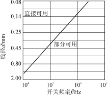
1. Introduction Monolithic switching power supply integrated circuits offer advantages such as high integration, excellent cost-performance, minimal peripheral components, and top performance. They can form isolated switching power supplies with high efficiency and no power frequency transformer. From 1994 to 2001, various single-chip switching power supply products like TOPSwitch, TOPSwitch-II, TOPSwitch-FX, TOPSwitch-GX, TinySwitch, and TinySwitch-II were introduced internationally. These have now become the preferred choice for medium and small power supplies, precision switching power supplies, and switching power modules. The high-frequency transformer is a crucial component for energy storage and transmission in switching power supplies. Its performance significantly affects power efficiency and other technical specifications, including electromagnetic compatibility (EMC). A high-efficiency high-frequency transformer should have low DC and AC losses, low leakage inductance, minimal distributed capacitance, and low coupling capacitance between windings. Below are key design considerations. 2. Reducing High Frequency Transformer Losses 2.1 DC Loss DC loss in a high-frequency transformer arises from copper loss in the coil. To improve efficiency, it's recommended to use thicker wires with a current density of J = 4 to 10 A/mm². 2.2 AC Loss AC loss is caused by skin effect and core losses. High-frequency currents tend to flow on the surface of the wire, increasing AC resistance. The penetration depth of the current is inversely proportional to the square root of the switching frequency. To reduce AC resistance, the wire radius should not exceed twice the skin depth. For example, at 100 kHz, a wire diameter of φ0.4 mm is theoretically acceptable, but using thinner wires wound in layers is more practical to minimize skin effect. Figure 1: Conductor wire diameter vs. switching frequency Core loss also affects efficiency. The AC flux density can be estimated by: BAC = (0.4π NP IP KRP)/2 δ Where BAC is in Tesla, NP and IP are primary turns and peak current, KRP is the ratio of pulsating to peak current, and δ is the air gap in cm. For continuous mode operation, BAC is typically 0.04–0.075 T, and core loss at 100 kHz should be less than 50 mW/cm³. 3. Minimizing Leakage Inductance Leakage inductance must be minimized to avoid high voltage spikes and increased drain clamp losses. For a transformer meeting insulation standards, leakage inductance should be 1%–3% of primary inductance. Measures to reduce it include reducing primary turns, increasing winding width, optimizing height-to-width ratio, minimizing insulation, and improving coupling. 3.1 Reduce Primary Turns and Increase Height-to-Width Ratio Selecting a suitable core shape and reducing primary turns while increasing height-to-width ratio can significantly lower leakage inductance. Using cores like EE or ETD, which have better ratios, is recommended. Triple insulated wire is ideal for high-performance applications due to its high dielectric strength and reduced volume compared to traditional enameled wire. 3.2 Winding Arrangement Concentric winding arrangements help reduce leakage inductance. For multi-output designs, the secondary with the highest output should be close to the primary. Foil windings and parallel winding techniques can enhance coupling. Proper layout minimizes distributed capacitance, which can cause ringing noise and reduce efficiency. 4. Suppressing High Frequency Transformer Audio Noise 4.1 Audible Noise Suppression Audible noise from high-frequency transformers is caused by magnetic forces and mechanical vibrations. Using specialized "glass beads" adhesive instead of epoxy improves bonding and reduces noise by up to 5 dB. This allows slight movement without affecting overall structure, minimizing deformation and noise. 4.2 Shielding To prevent interference, a copper shielding band can be wrapped around the transformer. This acts as a short-circuit ring, suppressing leakage magnetic fields and grounding the shield for optimal performance. 5. Conclusion The key design points for high-frequency transformers in single-chip switching power supplies are: (1) minimize losses, (2) reduce leakage inductance, and (3) suppress audible noise. These steps ensure higher efficiency, reliability, and performance in modern power systems. Turntable And Motor For Display And Toy Turntable and Motor for Display and children toys Turntable Motor,Toy Display,Record Player Motor AST Industry Co.,LTD , https://www.astsoundchip.com