LED display computer electronic clock This article refers to the address: http:// This example introduces a computer electronic clock (computer perpetual calendar) made with LEDs. The photo after the decoration is finished is as follows: LED driver chip please see: http:// After all the parameters are adjusted, if no key is pressed within five seconds, the number stops flashing and the setting adjustment state is exited. The source program list is as follows (no temperature display program): Start:do; 0e0h, 0feh, 0f6h, 00h); Clear:procedure; Send1302:procedure(comm); RBYT1: PROCEDURE; Send595_1:procedure; Rb1:procedure(abc,j); Rbyt6:procedure; Wbyt6:procedure; Display:procedure; /*jieya,yima,fasong*/ n=a(4); /* send date */ Do i=1 to 3; /* send second,minute,hour */ n=a(8); /* send 19 or 20 */ Beginset:procedure; Key:procedure; Main$program: Hotel Door Lock Motor also known as Smart Hotel Door Lock Motor, perform operations in the hotel door lock, at this point, the cardholder simply throw the door handle to open the door. That is to say the hotel Door Lock Motor is used to open the door.
Operating temperature range:
Hotel door Lock Motor should be used at a temperature of -10~60℃.
The figures stated in the catalog specifications are based on use at ordinary room temperature catalog specifications re based on use at ordinary room temperature (approximately20~25℃.
If a Smart Hotel Door Lock Motor is used outside the prescribed temperature range,the grease on the gearhead area will become unable to function normally and the motor will become unable to start.Depending on the temperature conditions ,it may be possible to deal with them by changing the grease of the motor's parts.Please feel free to consult with us about this.
Storage temperature range:
lock motor should be stored ta a temperature of -15~65℃.
In case of storage outside this range,the grease on the gearhead area will become unable to function normally and the motor will become unable to start.
Service life:
â—Use with a load that exceeds the rated torque
â—Frequent starting
â—Momentary reversals of turning direction
â—Impact loads
â—Long-term continuous operation
â—Forced turning using the output shaft
â—Use in which the permitted overhang load or the permitted thrust load is exceeded
â—A pulse drive ,e.g.,a short break,counter electromotive force,PWM control
â—Use of a voltage that is nonstandard as regards the rated voltage
â—Use outside the prescribed temperature or relative-humidity range,or in a special environment.
â—Please consult with us about these or any other conditions of use that may apply,so that we can be sure that you select the most appropriate model.
Hotel door lock motor applicable door types: building doors, fire doors, security doors, door and office door, fire doors, etc. Applicable scenario: family, company, office buildings, schools, shopping malls, such as Banks.
when it come to volume production,we're a major player as well .each month,we rurn out 600000 units,all of which are compliant with the rohs directive.Have any questions or special needed, please contact us, we have the engineer group and best sales department to service to you
Looking forward to your inquiry. Welcome to our factory.
Hotel Door Lock Motor Hotel Door Lock Motor,Smart Hotel Door Lock Motor,Hotel Keyless Door Lock Motor,Fingerprint Hotel Door Lock Motor Shenzhen Shunchang Motor Co., LTD. , http://www.scgearmotor.com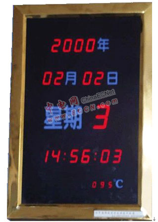
In the above picture, the year, month, day and time are selected as 1.2 inch common digital tube, the week is 2.3 inch digital tube, the temperature is 0.5 inch digital tube, or according to individual I like to use digital tubes with different specifications. The schematic is shown below: 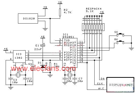
In the above figure, the CPU is AT89C2051, the clock chip is Dallas DS1302, the temperature sensor is Dallas digital temperature sensor DS1820, and the display driver chip is Texas Instruments TPIC6B595, which is also compatible with it. Chip NC595 or domestic AMT9595. The entire electronic clock uses two keys to adjust the time and date. One is the bit selection button and the other is the digital adjustment button. Press the bit selection button, the first two digits will start to flash and enter the setting adjustment state. At this time, press the number adjustment button, the current flashing digit can be changed.
$include(reg51.dcl)
Declare (sclk,io,rst) bit at (0b3h) register; /* p33,p34,p35 */
Declare (command,data,n,temp1,num) byte;
Declare a(9) byte;
Declare ab(6) byte;
Declare aco(11) byte constant (0fdh,60h,0dah,0f2h,66h,0b6h,0beh,
Declare week(11) byte constant (0edh,028h,0dch,7ch,39h,75h,0f5h,
2ch, 0fdh, 7dh, 00h);
Declare da literally'p15',clk literally'p16',ale literally'p17',
Mk literally'p11',sk literally'p12';
Sclk=0; io=0; rst=0;
End clear;
Declare (i,comm) byte;
Do i=0 to 7;
Comm=scr(comm,1);
Io=cy;
Call time(1);
Sclk=0;
Call time(1);
Sclk=1;
End;
End send1302;
Wbyt1:procedure(com,dat);/*byte write process*/
Declare (com,dat) byte;
Call clear;
Rst=1;
Call send1302(com);
Call send1302(dat);
Call clear;
End wbyt1;
Wbyt8:procedure;/*clock multibyte burst mode write process*/
Declare j byte;
Call clear;
a(7)=A(6); a(6)=a(0);
Rst=1;
Call send1302(command);
Do j=1 to 8;
Call send1302(a(j));
End;
Call clear;
End wbyt8;
DECLARE I BYTE;
CALL CLEAR;
RST=1;
Call send1302(0c1h);
IO=1;
DO I=0 TO 7;
SCLK=1;
SCLK=0;
CY=IO;
N=SCR(N,1);
END;
A(8)=N;
CALL CLEAR;
END RBYT1;
Send595:procedure;
Declare k byte;
Do k=0 to 7;
Data=scr(data,1);
Da=cy;
Clk=1;
Clk=0;
End;
End send595;
Declare k byte;
Do k=0 to 7;
Data=scr(data,1);
Da1=cy;
Clk1=1;
Clk1=0;
End;
End send595_1;
DECLARE (I, j, abc) BYTE;
CALL CLEAR;
RST=1;
Call send1302(abc);
IO=1;
DO I=0 TO 7;
SCLK=1;
SCLK=0;
CY=IO;
N=SCR(N,1);
END;
Ab(j)=N;
Ab(j)=dec(ab(j));
CALL CLEAR;
End rb1;
Call rb1(0f1h,0);
Call rb1(0f3h,1);
Call rb1(0f5h,2);
Call rb1(0f7h,3);
Call rb1(0f9h,4);
Call rb1(0fbh,5);
Call rb1(0fdh,6);
End rbyt6;
Call wbyt1(8eh,0); /* write enable */
Call wbyt1(0f0h,ab(0));
Call wbyt1(0f2h,ab(1));
Call wbyt1(0f4h,ab(2));
Call wbyt1(0f6h,ab(3));
Call wbyt1(0f8h,ab(4));
Call wbyt1(0fah,ab(5));
Call wbyt1(0fch,ab(6));
Call wbyt1(8eh,80h); /* write disable */
End wbyt6;
Rbyt8:procedure;/*clock multibyte burst mode read process*/
Declare (i,j) byte;
Call clear;
Rst=1;
Call send1302(command);
Io=1;
Do j=1 to 8;
Do i=0 to 7;
Sclk=1;
Call time(1);
Sclk=0;
Cy=io;
n=scr(n,1);
End;
a(j)=n;
End;
Call clear;
a(0)=a(6); a(6)=A(7);
a(0)=a(0) and 0fh;
If a(0)>6 then a(0)=0;
CALL RBYT1;
If (a(1)=0 and a(2)=0 and a(3)=0) then
Do;
Do num=0 to 35;
Call time(250);
End;
Temp1=1;
End;
If temp1=1 then
Do;
Temp1=0;
Ab(4)=ab(4)+1;
If ab(4)>99h then
Do;
Ab(4)=0;
Ab(5)=ab(5)+1;
If ab(5)>99h then ab(5)=0;
End;
Call wbyt6;
End;
End rbyt8;
Declare (i,n,m) byte;
n=a(0) and 0fh; /* send week */
Data=week(n);
Call send595;
n=n and 0fh;
Data=aco(n);
Call send595;
n=a(4);
n=shr(n,4);
Data=aco(n);
Call send595;
n=a(i);
n=n and 0fh;
Data=aco(n);
Call send595;
n=a(i);
n=shr(n,4);
Data=aco(n);
Call send595;
End;
Do i=5 to 6; /* send month,year */
n=a(i);
n=n and 0fh;
Data=aco(n);
Call send595;
n=a(i);
n=shr(n,4);
Data=aco(n);
Call send595;
End;
n=n and 0fh;
Data=aco(n);
Call send595;
n=a(8);
n=shr(n,4);
Data=aco(n);
Call send595;
Do m=0 to 5;
n=ab(m);
n=n and 0fh;
Data=aco(n);
Call send595_1;
n=ab(m);
n=shr(n,4);
Data=aco(n);
Call send595_1;
End;
Ale=0;
Ale=1;
End display;
a(0)=06h; a(1)=58h; a(2)=59h; a(3)=23h;
a(4)=30h; a(5)=06h; a(6)=97h; a(7)=00;
a(8)=19h; /* set date/time (1997,7,1,8:00:00,week 3) */
Call wbyt1(8eh,0); /* write enable*/
Call wbyt1(80h,00h);/* start colock */
Call wbyt1(0beh,0abh);/*Two diodes are connected in series with 8K resistors*/
Command=0beh; /* write colock/date */
Call wbyt8;
Call wbyt1(0c0h,a(8));
Call wbyt1(8eh,80h); /* set write protect bit */
End beginset;
Declare (i, time1, k1, tem) byte;
Call time(100);
K1=7; time1=30;
If mk=0 then
Do;
Do while time1>0;
Week: if k1=0 then
Do;
Do i=0 to 5;
/* call hz(a(0)); */
End;
Do i=0 to 3;
/* call hz0; */
End;
End;tem=a(k1);
If k1=7 then tem=a(8);
a(k1)=0aah;
If k1=7 then a(8)=0aah;
Call display;
Call time(254);
Call time (254);
a(k1)=tem;
If k1=7 then a(8)=tem;
Call display;
Call time(254);
Call time(254);
Call time(254);
Time1=time1-1;
If mk=0 then
Do;call time(100); /*MOD KEY PROCESS*/
TIME1=30;
IF MK=0 THEN
DO;
K1=k1-1;
DO WHILE K1=0FFH;
K1=7;
END;
END;
End;
IF SK=0 THEN
DO;CALL TIME(100); /*SET KEY PROCESS*/
TIME1=30;
IF SK=0 THEN
DO;
Tem=tem+1;
Tem=dec(tem);
DO CASE K1;
DO WHILE tem=7;/*week*/
Tem=0;
END;
DO WHILE tem=60H;/*scond*/
Tem=0;
END;
DO WHILE tem=60H;/*minute*/
Tem=0;
END;
DO WHILE tem=24H;/*hour*/
Tem=0;
END;
DO WHILE tem=32H;/*date*/
Tem=1;
END;
DO WHILE tem=13H;/*month*/
Tem=1;
END;
DO while tem=100h; /* YEAR */
Tem=00;
END;
DO WHILE TEM>=21H;
Tem=19H;
END;
END;
A(K1)=tem;
If k1=7 then a(8)=tem;
END;
END;
END;
END;
End key;
Mk=1; sk=1; temp1=0; num=0; p32=1;
If sk=0 then call beginset;
Clk=0;da=0;ale=1;
Loop:
Do while mk=1 ;
If a(0)>6 then a(0)=0;
Command=0bfh;
Call rbyt8;
Call display;
Do while mk=0;
Call key;
Call wbyt1(8eh,0);
Command=0beh;
Call wbyt8;
Call wbyt1(0C0H,A(8));
Call wbyt1(8eh,80h);
End;
End;
Goto loop;
End start
Induction door lock is a infrared sensor through induction of new security equipment, widely used in hotels, hotels and clubs, and other areas of the smart IC card, rf door lock, generally divided into induction induction door lock system, provides the high quality for the hotel induction door lock system. Induction in the European and American countries have been developed to a certain extent, has been a measure of the quality of life index of height and life.
