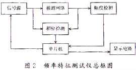
1 Introduction The frequency characteristic refers to how a system or component responds to a sinusoidal input signal at different frequencies. As illustrated in Figure 1, the system under test receives a sinusoidal input with amplitude Ar and angular frequency ω. If the system is linear, its steady-state output remains a sinusoidal signal with the same frequency ω but a different amplitude Ac and a phase difference φ. By varying ω, a series of input-output data can be collected. The ratio of the output amplitude to the input amplitude, A(ω) = Ac/Ar, is known as the amplitude-frequency characteristic of the system. It is commonly expressed in logarithmic form as 20 lg A(ω). The relationship between the phase difference φ(ω) and the frequency ω is called the phase-frequency characteristic. Together, these two characteristics are referred to as the frequency response. One of the most common tools used to represent this is the Bode diagram, which displays the open-loop frequency characteristics of a system. To determine the frequency characteristics of a system, a frequency sweep tester is typically used. This device, also known as a frequency sweeper, measures the amplitude-frequency characteristics of the network under test. It can detect parameters such as resonant frequency, bandwidth, out-of-band attenuation, and gain, making it an essential tool in the electronics field. Traditional analog sweepers are expensive, lack direct phase measurement capabilities, and cannot store or print frequency response graphs, which makes them inconvenient for users. Therefore, digital frequency sweepers have become a more practical solution. 2 Overall Design The system uses a microcontroller to generate a standard sine wave signal, which is then fed into the network under test. The output from the network is processed by both an amplitude detection circuit and a phase detection circuit. These circuits measure the peak value and phase difference, respectively, and send the data back to the microcontroller for processing. The results are displayed in real-time on an LED screen and stored in memory for later display on an oscilloscope to visualize the amplitude and phase frequency curves. The overall system architecture is shown in Figure 2. 2.1 Design of the Frequency Sweep Signal Source The frequency sweep signal generator is the core component of the frequency characteristic tester. It provides a periodic sinusoidal signal over a specific frequency range that is required for testing. Several methods can be used to generate such signals, including phase-locked loops (PLL), programmable prescalers, integrated waveform generators, dedicated frequency synthesizers, and direct digital frequency synthesizers (DDS). In this design, a single-chip microcontroller is used along with EDA technology to implement a DDS using an ispCPLD chip. Direct Digital Frequency Synthesis (DDS) is a fully digital method that offers high-speed frequency conversion, fine frequency resolution, and low phase noise. It maintains phase continuity during frequency changes and is ideal for implementing frequency, phase, and amplitude modulation. The key components of a DDS include a phase accumulator, a sine wave lookup table (ROM), and a digital-to-analog converter (DAC). The phase accumulator is the heart of the system, consisting of an N-bit binary adder and an N-bit register controlled by a clock signal fclk. When the phase increment is set to 1, and the accumulator has a 32-bit word width, the output address corresponds to a phase resolution of 1/2³². The sine wave ROM stores a lookup table of sine values, and each instantaneous phase code corresponds to a specific amplitude code. During operation, the control word is loaded into the DDS, converted into a phase value, and then used to generate the corresponding amplitude code through the DAC. The output is filtered using a low-pass filter to produce the final sine wave. Additionally, the analog sine wave is compared with a threshold voltage to generate a square wave of the same frequency. This square wave is used to synchronize the system and ensure accurate sampling of the desired sine wave. The output frequency f₀ of the signal generator is given by: where fc is the crystal frequency, k is the division ratio, N is the number of bits in the phase accumulator, and M is the phase increment. In this design, fc = 32.768 MHz, k = 50, and N = 16. Substituting these values into the formula gives: Thus, by controlling the value of M, the system can achieve a frequency step of 10 Hz accurately. The clock frequency is calculated as: where △phase is the frequency control word, sysclk is the system clock, clkin is the reference clock frequency for the DDS, N is the number of bits in the frequency register, and M is the number of bits in the phase offset register. The frequency control word △phase determines the output frequency, while the frequency resolution is determined by the number of bits N in the frequency register. The higher the value of N, the finer the frequency resolution. The phase resolution depends on the number of bits in the phase offset register, and the amplitude resolution is determined by the accuracy of the DAC. Contact Switch,Reed Contact Switch,Magnetic Contact,Magnetic Contact Switch Shanghai Janetec Electric Co., Ltd. , https://www.janetecelectric.com

![]()
![]()

 [1] [2]