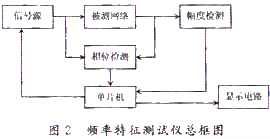
1 Introduction The frequency characteristic is a key concept in system analysis, representing how a system responds to sinusoidal input signals at different frequencies. As shown in Figure 1, the system under test receives a sinusoidal signal with amplitude Ar and angular frequency ω. If the system is linear, its steady-state output will also be a sinusoidal signal with the same frequency ω but possibly a different amplitude Ac and a phase difference φ. By varying ω, a series of input-output data can be collected. The ratio of the output amplitude to the input amplitude, A(ω) = Ac / Ar, is called the amplitude-frequency characteristic. Typically, 20 log A(ω) is used as the logarithmic amplitude-frequency characteristic. The relationship between the phase difference φ(ω) and ω is referred to as the phase-frequency characteristic. Together, these two characteristics are known as the frequency characteristic. One of the most common tools for visualizing this is the Bode diagram, which is widely used for open-loop frequency analysis. Frequency characteristic testers, often called frequency sweepers, are essential instruments for analyzing the behavior of electrical networks. These devices measure parameters such as resonant frequency, bandwidth, out-of-band attenuation, and gain. Traditional analog sweepers, while effective, are costly and lack the ability to directly capture phase information or store and print frequency response graphs. This limitation has led to the development of digital frequency characteristic testers, which offer greater flexibility and functionality for modern users. 2 Overall Design The system is based on a single-chip microcontroller that generates a standard sine wave, which is then fed into the network under test. The output from the network is processed through an amplitude detection circuit and a phase detection circuit. The detected peak values and phase differences are sent back to the microcontroller for processing. The results are displayed in real-time on an LED display and stored in memory for later use by an oscilloscope to plot the amplitude and phase frequency curves. The overall architecture is illustrated in Figure 2. 2.1 Design of the Frequency Sweep Signal Source The frequency sweep signal generator is the core component of the frequency characteristic tester. It provides a sine wave whose frequency changes over a specific range, allowing for comprehensive testing of the network's response. Common methods for generating such signals include using phase-locked loops (PLLs), integrated waveform generators, and direct digital synthesis (DDS). In this design, a programmable logic device (ispCPLD) is used along with EDA technology to implement a DDS-based system, enabling precise and flexible frequency generation. Direct Digital Frequency Synthesis (DDS) is a fully digital method that offers high speed, precision, and low phase noise. It maintains phase continuity during frequency changes, making it ideal for applications requiring accurate modulation. The main components of a DDS system include a phase accumulator, a sine wave lookup table (ROM), and a digital-to-analog converter (DAC). The phase accumulator, which is central to the system, uses a binary adder and register to perform linear accumulation based on a frequency control word. The output address corresponds to the phase resolution of the waveform, and the DAC converts the digital samples into an analog signal, which is then filtered to produce a clean sine wave. The output frequency f₀ of the signal generator is calculated using the formula: Where fc is the crystal frequency, k is the division ratio, N is the number of bits in the phase accumulator, and M is the phase increment. In this design, fc = 32.768 MHz, k = 50, and N = 16. Substituting these values gives: This allows for a frequency step of 10 Hz, meeting the system's requirements. The clock frequency is calculated as: Where △phase is the frequency control word, sysclk is the system clock, clkin is the reference clock frequency for the DDS, N is the bit width of the frequency register, and M is the bit width of the phase offset register. The frequency control word determines the output frequency, while the number of bits in the frequency and phase registers affects the resolution. The D/A converter’s accuracy also influences the amplitude resolution. Timing Belt,Lift Door Machine Belt,Elevator Door Machine Belt,Elevator Timing Belt Shanghai Janetec Electric Co., Ltd. , https://www.janetecelectric.com

![]()
![]()

 [1] [2]
