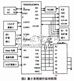
introduction As a combination of high-tech and new technology, intelligent robot directly reflects the development level of a country's information technology and has been highly valued by all sectors of society. Intelligent robots involve almost all aspects of information technology, allowing students to access and see the panoramic view of information technology, and intelligent robots are an open platform for information technology, students can fully use their imagination to develop a variety of smart devices, thus cultivating students The ability to develop information technology, in the development process, to develop a variety of abilities to stimulate students' interest. The TMS320LF2407A educational robot hardware platform based on smart car is designed in this paper, including the power module and motor drive module circuit design, and integrates infrared and photosensitive sensors and wireless data transmission module. Through software design, tracking and obstacle avoidance can be realized. The combination of tracing and obstacle avoidance has achieved the goal of combining theoretical study with hands-on practice, consolidating knowledge and further enhancing the interest of learners. 1 Design ideas and overall plan 1.1 The design idea of ​​educational robot The educational robot uses the TMS320LF2407A microcontroller as the core. The external environment information collected by various sensors such as infrared sensor and photoelectric sensor is used as the input signal. The DSP performs arithmetic processing and uses PWM technology to output and adjust the speed and direction of the car in real time to realize the car. Automatic control functions such as tracing, obstacle avoidance, tracing, and obstacle avoidance, and the car has been traced When encountering obstacles in the process, when the tracking and obstacle avoidance algorithm can not complete the obstacle avoidance function while tracing, the wireless communication transceiver module connected to the PC and another wireless transceiver module connected to the DSP can realize wireless short-distance communication. , control the car out of the obstacle zone and carry out normal tracing. 1.2 Overall design and block diagram The overall block diagram of the robot car system is shown in Figure 1. It mainly consists of the TMS320LF2407A minimum system part, power supply module, motor drive module, sensor module and wireless communication module, which realizes the continuous transmission of information from various sensors on the vehicle to the on-board microcontroller. And download the programming design algorithm to the microcontroller to real-time adjust the motion state of the car to complete certain functional requirements. 2 system hardware module design 2.1 TMS320LF2407A minimum system design The TMS320LF2407A is the most widely used product in the 2000 series. It not only has an efficient processor for digital signal processing, but also integrates a rich set of on-chip peripherals for memory and adaptive control applications, thus forming a basic On-chip computer system. In addition to the improved Harvard architecture, multi-bus architecture and pipeline structure, it also uses high-performance static CMOS technology, the voltage drop is 3.3V, reducing power consumption, instruction execution speed is increased to 40MIPS, almost all instructions can be 2 5ns is completed in a single cycle. The basic structure of the TMS320LF2407A consists of three components: a central processing unit (CPU), memory, on-chip peripherals, and dedicated hardware circuitry. The hardware platform of the system makes full use of the characteristics of the TMS320LF2407A controller to adopt modular design, which is divided into basic circuit and extended control circuit. The basic circuit includes a power supply circuit, a reset circuit, a clock circuit, an A/D input channel, and a JTAG emulation circuit. The expansion circuit includes a memory and a decoding circuit, a serial communication SCI and RS-232 interface circuit, a CAN interface circuit, an SPI function module, and the like. The system hardware block diagram is shown in Figure 2.
Wire Packaging Spool, Magnet Wire Reel, Magnet Wire Spool, Packing Wire Spool NINGBO BEILUN TIAOYUE MACHINE CO., LTD. , https://www.spool-manufacturer.com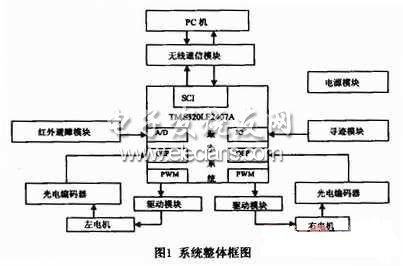
2)High speed custom labeling and printing on flanges available – even on short runs
3)One piece molded construction for strength and precision
4)Appealing designs as well as ergonomics (no sharp edges)
Type
Weight
(gram)
d1
(mm)
D1
(mm)
d2
(mm)
D2
(mm)
H1
(mm)
H2
(mm)
d3
(mm)
A1
(mm)
A2
(mm)
d4
(mm)
E
(mm)
PC-70
40
70
38
70
85
20
7
7
PC-80
70
80
50
64
80
20
8
8
7
20
PC-83
70
83
45
100
120
20
10
10
PC-100A
110
100
45
70
88
20
9
9
PC-100B
100
100
45
100
120
20
10
10
PC-125A
180
125
65
100
120
20
10
10
7
20
PC-125B
170
125
70
100
120
20
10
10
PC-130A
200
130
65
100
120
22/25
10
10
PC-130B
210
130
65
100
120
22
10
10
SH-16
230
150
90
100
124
30
12
12
12
26
PC-185A
400
185
128
155
178
30
11
11
PC-185B
500
185
128
155
178
30
11
11
PC-185C
500
185
130
160
180
30
10
10
PC-220A
660
220
110
155
185
40
15
15
12
42
PC-220B
660
220
110
155
185
38
15
15
15
38
PC-220C
660
220
110
155
185
30
15
15
14
38
PC-250
870
250
110
155
185
40
15
15
12
42
PC-300A
1400
300
180
170
200
32
15
15
17
45
PC-300B
1400
300
180
170
200
100
15
15
20
125
PC-355
1950
355
224
160
200
36
20
20
26
50~80
PC-410
4550
410
310
180
228
70
24
24
PC-500A
8450
500
315
180
250
40
35
35
26
70~100
PC-500A1
8450
497
315
180
250
40
35
35
26
70~100
PC-500B
8600
500
250
250
300
56
25
25
26
70~100
PC-500B2
9020
500
250
240
290
40
25
25
26
70~100
PC-500C
8600
500
250
235
300
56
20
20
26
70~100

Significant product benefits:
1)A full line of spools in a variety of standard sizes