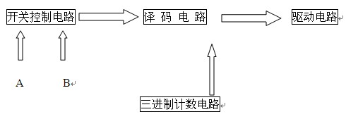
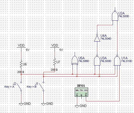
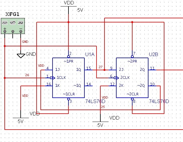
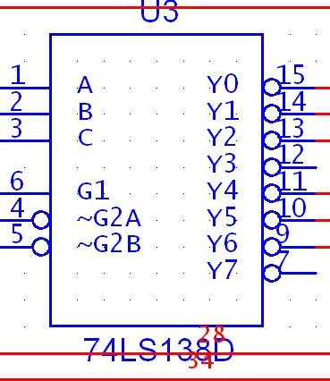
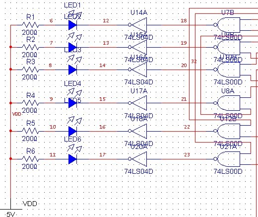
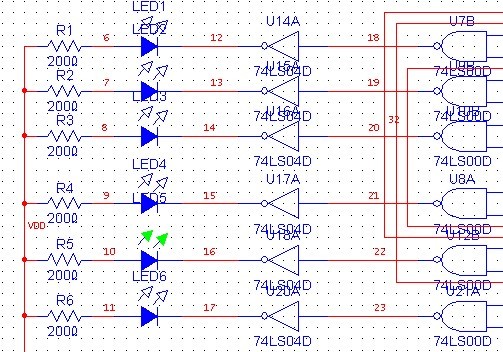
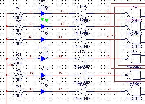
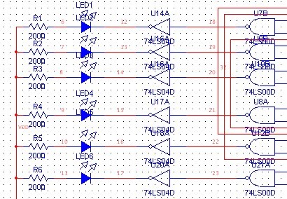
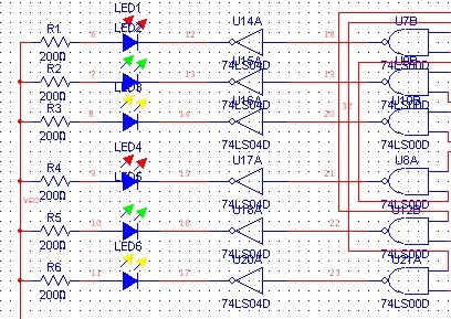
This paper designs a design of vehicle taillight control based on Multisim , which requires the lighting and extinction of taillights under the conditions of left turn, right turn and stop. Multisim has a computer to simulate various circuit functions, and it can achieve the same functional effects of real devices by using various simulation devices. Design requirements Assume that there are three indicator lights on the left and right sides of the rear of the car (simulated by LED) 1. When the car is running normally, the indicator light is completely off; 2. When the left turn is turned, the three left indicators are lit in the order of the left cycle; 3. When the right turn is turned, the three lights on the right side are lit in the right cycle order; 4. When the brake is temporarily applied, all the indicators flash at the same time. The design includes using a master-slave JK trigger to form a 3-digit counter to provide pulse for the design of the left (right) loop flashing control circuit for the taillights of the car; and using the 74LS138D3 line-8-line decoder to control the illumination of the indicator Happening. Design a switch control circuit to control the flicker of the taillights and determine the operation of the 74LS138D decoder. General circuit diagram 1. Automobile taillight control circuit Figure 1 car taillight control block diagram Figure 1 is a block diagram of the vehicle taillight control circuit. The more complicated one is the ternary counting circuit and the decoding circuit. The switch control circuit is controlled by two switches to control the drive circuit by controlling the signal provided by the decoding circuit. The ternary counter circuit is composed of two master-slave JK flip-flops, and the timing logic circuit is formed by the characteristics of the master-slave JK flip-flop. To achieve ternary counting; the decoding circuit uses a 74LS138D decoder, which can control the output of 8 ports using a 3-wire 8-wire decoder. In this experiment, only 6 ports need to be used, and the other two ports are idle. The logic state of the six ports of the decoder is controlled by a ternary counter and a switch control circuit; the driving circuit adopts a common LED tube, adopts a common anode form, the positive pole of the LED tube is connected with a +5V voltage, and the negative pole controls the LED through a driving circuit. The light is off. 2. Circuit structure and schematic (1) Switch control circuit (Figure 2) Figure 2 switch control circuit One end of the switch is connected to a high level, and one end is grounded (low level). The 74LS86D is connected to the input control terminal of the 74LS138. When the switch is closed or open at the same time, the input is the same, and the 74LS86 output is “0â€, then the 74LS138 is not decoded. If the two switches are disconnected at the same time, the output of 74LS04D is "1"; and 74LS10D is connected with CP pulse, so the output of 74LS00D is completely determined by CP pulse; when both switches are closed at the same time, the output of 74LS00D is "1"; B switch Open; B switch is closed, and the analysis when A switch is turned on is also analyzed according to the above method. (2) ternary counter circuit (Figure 3) Figure 3 ternary counter circuit The ternary counting circuit consists of two master-slave JK flip-flops. The output Q1 of the first master-slave JK flip-flop is directly connected to the input of the 74LS138 decoder, and the input of the second master-slave JK flip-flop is also directly connected to the input of the 74LS138, and the second The other end of the main slave JK flip-flop outputs directly as the J-side input of the first master-slave JK flip-flop. Note that Q2 should be higher than the Q1 weight. Moreover, the K-terminal inputs of the two master-slave JK flip-flops are all connected high, so that the period of the changed pulse is 3, thereby achieving ternary counting. (3) Decoding circuit (Figure 4) Figure 4 decoding circuit The 74LS138 decoder is a commonly used 3-wire 8-wire decoder. As shown in the figure, the 4th and 5th terminals are grounded, and the 6-terminal control circuit provides the control signals. 1, 2, and 3 respectively. The output signals Q1, Q2 of the two master-slave JK flip-flops and the control signals of the control circuit. Since only six indicators are required, only six ports (left turn: Y0 Y1 Y2; right turn: Y4 Y5 Y6) are connected to the output of the 74LS138 to control the signal. And, according to the following truth table to achieve. Switch control Trimetric counter 6     One    Means    Show    light A     B Q1    Q2 D0     D1     D2     D4     D5     D6 0     0     CP     CP     CP     CP     CP     CP 0     1   0     0   0     1   1     0   0       0       0      1       0      0   0       0       0      0       1      0   0       0       0      0       0      1 1     0   0     0   0     1   1     0   0       0       1      0       0      0   0       1       0      0       0      0   1       0       0      0       0      0  1     1   0       0       0      0       0      0 (4) Drive circuit: as shown in Figure 5 Figure 5 drive circuit Light-emitting diodes are used to display the results of the operation. The LED is positively connected to the 5V power supply. When the right input of the non-gate is high level, the LED turns on after the non-gate, and the LED is bright. When the right input of the non-gate is low, the After the non-gate turns high, the LED is extinguished. 3. Calculation, simulation process and results The circuit runs in each case: â—‹1 When the A switch is closed and the B switch is open (ie, logic 10), the result is as follows: Figure 6 A switch is closed, B switch is open and running â—‹2 When the A switch is turned on and the B switch is closed (ie, logic 01), the operation result is as follows: Figure 7 A switch is open, B switch is closed. â—‹3 The operation results when A and B switches are closed at the same time (ie logic 11) are as follows: Figure 8 A, B switch simultaneously closed operation results â—‹4 When the A and B switches are turned on at the same time (ie, logic 00), the results are as follows: Figure 9 A, B switch simultaneously open the operation result map 4. List of components yuan  Piece regulation  grid number  the amount Function signal generator XFG1 1 set Master-slave JK trigger 74LS76D 2 Double input NAND gate 74LS00D 8 Three-input NAND gate 74LS10D 1 Double input non-gate 74LS04D 7 Double input XOR gate 74LS86D 1 decoder 74LS138D 1 resistance 200 Euro 8 DC power supply 5V 6 Ground terminal GND 4 5. Design and use instructions This design is based on the computer Multisim simulation software to simulate the state, through the switch A, B to achieve the state transition, A, B simultaneously closed the equivalent of the car brake, the six indicators are flashing at the same time; A, B at the same time disconnected equivalent to the car Normal operation, all indicators are off; A closed, B disconnected is equivalent to the left turn of the car, the left three lights flash in the left cycle; A disconnected, B closed is equivalent to the car right turn, the right three lights are right The cycle flashes. The "XFGI" frequency is suitable for 60HZ. Therefore, the design basically has the basic functions of the common taillight control of the automobile, and realizes the functions of turning and braking indication, and has certain use value. Design summary In this design, the more difficult section is to design the ternary counter circuit, and the control circuit and its connection problem with the decoder is more complicated. I think that the switch A is connected to the decoder port C. And outputting Y3 is very clever. There is also a small detail in the connection between the decoder and the driving circuit, that is, the indicator on the left side should be flashed in the left loop mode, that is, the flashing from D2 to D0, then the decoder output port Y0 , Y1, Y2 should be connected to the indicators D2, D1, D0. [1]. 74LS138 datasheet http://
Spi Led Pixel Light can get the matrix light, Led Video Wall, Flexible Led Screen effect with our different dimension from 30mm up to 120mm with different pixel space. We have the 20mm matrix light, 30mm matrix light, 50mm matrix light. All of them use the SMD RGB 5050 led lamps. Of course, the led matrix can be made with other color SMD led lamps. You can use them to make the indoor video mall or outdoor video wall displays. What's more, the led matrix lights are also for the signs, such as decorations for building outline, amusement part, outdoor billboard, LOGO, square and street, stage, hotel, bar and disco, etc.
Photo show of SPI LED Pixel Light:
SPI LED Pixel Light Spi Led Pixel Light,Spi Programmable Pixel Led Light,Led Video Wall,Flexible Led Screen Shenzhen Iseeled Technology Co., Ltd. , https://www.iseeledlight.com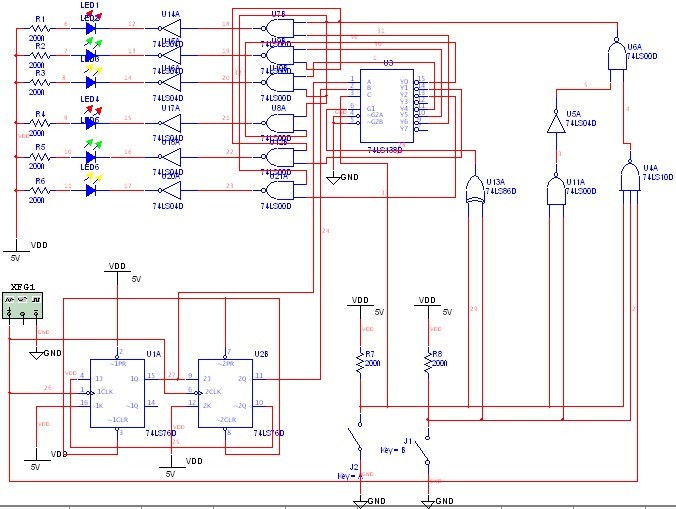
references:
[2]. 74LS86 datasheet http://
[3]. 60HZ datasheet http://

16 times
Window._bd_share_config = { "common": { "bdSnsKey": {}, "bdText": "", "bdMini": "2", "bdMiniList": false, "bdPic": "", "bdStyle": " 0", "bdSize": "24" }, "share": {}, "image": { "viewList": ["qzone", "tsina", "tqq", "renren", "weixin"], "viewText": "Share to:", "viewSize": "16" }, "selectShare": { "bdContainerClass": null, "bdSelectMiniList": ["qzone", "tsina", "tqq", "renren" , "weixin"] } }; with (document) 0[(getElementsByTagName('head')[0] || body).appendChild(createElement('script')).src = 'http://bdimg.share. Baidu.com/static/api/js/share.js?v=89860593.js?cdnversion=' + ~(-new Date() / 36e5)];