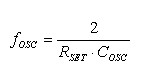
introduction This article refers to the address: http:// The High Intensity Discharge (HID) lamp actually includes a large class of lighting products that use small high internal pressure arc tube illumination. There are basically three types: mercury vapor (MV) lamps, metal halide (MH) lamps, and High and low pressure sodium (HPS or LPS) lamps. HID lamps all operate on a discharge principle similar to that of fluorescent lamps: when the gas filled in the lamp, such as when the current supplied by the ballast is activated, it illuminates. The car halide lamp ballast system is mainly composed of a DC-DC converter including a 9-16V automotive lead sulfate battery, a high voltage igniter, a 200-400 Hz full bridge inverter, and a control circuit for ensuring steady state power output. Part of the composition (Figure 2). The DC/DC converter must be capable of outputting 60-500V DC current in the input voltage range of 9-16V, and has input overvoltage, output short/open and overcurrent protection. The function of the igniter is to generate an instantaneous high voltage 20-30KV breakdown lamp discharge. The full-bridge inverter provides the driving signal of the 200-400Hz full-bridge power switch tube, completes the DC-AC inverter, realizes the voltage polarity reversal at both ends of the lamp tube, prevents the single-end blackening of the lamp tube, and prolongs the life of the lamp tube. The control circuit serves to ensure a constant power output to the steady state of the lamp. When the voltage is stabilized, the voltage drop across the lamp is about 60-110V. If the 35W lamp is steady state, its power must be within the range of 35W±2W. If the power is too high, the lamp will be damaged and the lamp life will be shortened. Too low will reduce the output brightness and cause driving safety hazards. 1 Introduction to UCC2305 UCC3305 is an integrated circuit drive control chip designed for automotive HID lamp applications. The UCC3305 integrates all the functions required to control and drive HID lamps. It can meet the requirements of quickly opening the headlights of the car, and other options for HID. Lighting equipment for lights. It has the following performance requirements for automotive HID ballast design: ·Full bridge drive output · With input overvoltage, output overcurrent and overvoltage protection · Constant power output control for different lamp voltages · Current type PWM controller with frequency up to 300KHz ·Light cooling, hot start current adjustable and normal working current control · 9-16V input voltage wide operating range and fast start-up characteristics as low as 6V ·40°-105°C wide temperature working range meeting automotive electronics requirements The typical application circuit analyzes the external pin diagram, which is briefly described as follows: 5VREF—Internal 5V reference, UCC3305 is used to set current and threshold. It can also be used for other functions. ADJ—The voltage of this pin can be adjusted to control the ratio of the peak current of the cold lamp to the peak current of the warm lamp. This voltage is determined by the resistance connected from ADJ to GND. BAT—Used to detect excessively high input voltages and turn off the integrated circuit when the input exceeds a predetermined level. This pin should be connected to a voltage divider that is connected across the input supply to the "ground". When the input voltage exceeds 5V, the UCC3305 is turned off. To protect the integrated circuit in very high or negative input conditions, the voltage divider must be kept above 10k. BOOST—Although the UCC3305 is powered by the input VCC, most of the device's functionality relies on a supply voltage of approximately 10V to BOOST. The 10V power supply voltage can be generated by using PUMPOUT as the AC signal and the external diode as the voltage doubler of the switch. BYPASS—The pin is externally connected to a large storage Capacitor to provide charging and discharging of the capacitors at the SLOPEC and WARMUPC pins. The lamp temperature change is compensated by the voltage change on the SLOPEC and WARMUPC pin capacitors. Assuming that the maximum current flowing through the BYPASS pin is 5μA, the discharge time is 60s, and the maximum allowable voltage drop is 5V, the BYPASS external capacitor can be estimated as follows: COMP—Normally this port is connected to the FB terminal via a capacitor. When there is a difference between the commanded power of the lamp and the desired power, the error amplifier will be amplified a second time. The amplifier senses the difference between FB and 2.5V and drives the COMP with the amplified error voltage to compensate the overall feedback loop to keep the system stable. DIVPAUSE—The QOUT and QOUT of the UCC3305 are the ports used by the AC ballast for lamp polarity switching. In order for the arc to form in the correct place between the electrodes, it is important to stop the polarity switch after the lamp is ignited. Raising the DIVPAUSE potential stops the internal divider from generating QOUT and QOUT signals, which freezes the QOUT and QOUT signals. To do this, connect a resistor from NOTON to DIVPAUSE and a capacitor from DIVPAUSE to GND. FLTC—Because the voltage at the VOUTSENSE pin is proportional to the lamp voltage, the voltage is too high or too low and the lamp will be open, shorted or not working. During normal operation, the FLTC is connected to a capacitor and discharged to 0V through the UCC3305 internal current source. The UCC3305 monitors the voltage at VOUTSENSE and compares it to an internal low threshold of 83 mV and a high threshold of 2V. As long as the voltage at pin VOUTSENSE exceeds the internal high and low threshold windows, approximately 250nA of current pulls the FLTC. If the fault persists for a long time, the FLTC external capacitor charges more than 5V, indicating that the controller has been shut down due to a catastrophic failure, and this state is maintained until the BOOST terminal is powered off. The FB-UCC3305 internal error amplifier amplifies the difference between the lamp command power and the desired power, senses the difference between FB and 2.5V, and drives COMP with the error voltage. ISENSEIN—This pin is connected to the current sense resistor to sense the battery current. The power adjustment algorithm in the UCC3305 controller calculates the current and voltage of the lamp and sends a battery current suitable command to maintain the lamp power constant. Many functions of the ISET-UCC3305 require precise control of the current. This pin is connected to the GND to adjust the idling current. The normal operating current of the UCC3305 corresponds to a resistance of approximately 100k. LOADISENSE—just as ISENSEIN is connected to the sense resistor to monitor the battery current, and the LOADISENSE is connected to the sense resistor to monitor the lamp current. Combines the lamp voltage sensed by VOUTSENSE. The controller will give the power supplied to the lamp at different temperatures. LPOWER-LOADISENSE directly drives the input of an op amp in the UCC3305, amplifies the difference between the expected and actual value of the load current and produces an output signal fed to the error amplifier at LPOWER. NOTON—The lamp is under error conditions. If the lamp voltage is too high or low, the NOTON pin potential will be raised to VCC. When the VOUTSENSE pin voltage is within the 83mV to 2V window, the NOTON potential is pulled low. OSC—This pin is connected to GND to set the frequency of the PWM in the UCC3305. A typical 200pF capacitor has a frequency of 100kHz. PUMPOUT—Although the UCC3305 is powered by VCC, most of the device's functions are derived from a supply voltage of approximately 10V connected to BOOST. The 10V power supply voltage is generated by using PUMPOUT as an AC signal and an external diode as a voltage doubler for switching. The PUMPOUT output is a square wave with a swing from VCC to GND and a frequency half of the OSC frequency. PWMOUT—The output of the pulse width modulator. In normal systems, PWMOUT can be directly connected to the N-channel power MOSFET gate. QOUT—The logic output of the oscillator frequency is 180 degrees out of phase with QOUT. SLOPEC—To track the heating and cooling of the lamp, the UCC3305 must be connected to both the charging and discharging capacitors. One is connected to SLOPEC and charged to 5V at a rate controlled by ISET to GND resistor. When VCC is de-energized, SLOPEC discharges at a nominal 100nA constant current. Another connection to WARMUPC. VCC—The main power supply for the UCC3305. It should normally be located at 6.8V through an external Zener diode clamp. VOUTSENSE—This pin is used to sense the lamp voltage through a 120:1 voltage divider. The normal operating HID lamp has a lamp terminal voltage between 60V and 110V. A lamp above 300V will break down, so the input voltage of the starter must be limited to a maximum of 600V. A lamp voltage below 10V indicates that the lamp is shorted. WARMUPC—The voltage at the pin connected to GND can estimate the temperature of the lamp. When the lamp is lit, the capacitor is first charged to 4.2V by the 200nA current source, and then charged from 4.2V to 10V by the 100nA current source. When the lamp is extinguished, the capacitor is first discharged from the 39nA current sink to 2.5V, and then discharged by the 11nA current sink. GND. The voltage of the WARMUPV-WARMUPC port is used to modulate the signal fed through the FB to the error amplifier. However, the direct use of the impedance is too high. The UCC3305 contains a buffer amplifier that buffers the WARMUPC voltage and sends it to WARMUPV to make the signal suitable for driving FB. 2 Typical application circuit analysis The output of the ballast is a full bridge inverter structure. The output DC of the flyback converter is guided to the AC lamp through the output stage of the full bridge inverter structure. The full bridge output stage operates with a typical 195 Hz low frequency switching obtained from the PWM oscillator, so the average lamp voltage is zero. The UCC3305 has a logic output called NOTON, which is high when the lamp is not running (NotOn) and low when the lamp is running. Since this output is connected to the DIVPAUSE input, this low frequency switching is terminated when the lamp is fully illuminated. The UCC3305 control IC has two low frequency outputs: QOUT and QOUT, each with the ability to drive the low-side MOSFET directly at 195 Hz. High-side MOSFETs require level shifting. The LPOWER output of the UCC3305 is a voltage that is roughly proportional to the input power of the lamp. The UCC3305 is capable of constant power regulation of the lamp over a wide range of lamp voltages. The range of lamp voltages that produce constant lamp power is set by limiting the VOUTSENSE port amplifier. When the VOUTSENSE input is below 0.5V, just as the lamp is shorted, the loop regulates the load current to make it constant. When the input of VOUTSENSE is higher than 0.82V, the lamp is open or not ignited, and the loop is also regulated by the load current, but less than the short circuit condition. Between the above, the amplifier driving the LPOWER pin will add the load current and load voltage and produce a signal that is roughly proportional to the load power. In addition to the complete current-mode PWM, the UCC3305 also includes rate skew compensation, a very valuable feature to improve current loop stability. The rate skew compensation is achieved by the sawtooth current in the chip and the off-chip RSL resistor. The larger the RSL value, the larger the slope compensation given and the more stable the feedback loop. In this typical application, the UCC3305 draws power from a 6.8V Zener. The Zener can also provide overvoltage protection with fewer components and lower cost, and reverse battery protection. The output of the Zener tube drives the VCC pin of the UCC3305. VCC is input to the UCC3305 charge pump. The charge pump produces a 10V regulated supply voltage at the BOOST output to drive all other functions of the UCC3305. Considering that the most significant stress in the automotive environment is the overvoltage that occurs during load switching and sudden start-up of the dual battery, because the voltage entering the ballast at this time may be high enough to damage the power level of the deliberate design. The supply voltage UCC3305 adjusted by the Zener tube has inherent immunity to this type of damage. In addition, the UCC3305 can also protect the ballast components by turning off the PWM when an overvoltage occurs at the BAT input. The bias current of all UCC3305 circuits is set by the ISET to ground resistance, which should be between 75k and 150k under optimal conditions. The oscillator frequency in the HID lamp controller UCC3305 is set by the resistance and capacitance from ISET to ground. The oscillator oscillation frequency can be estimated by: At an oscillation frequency of 100 kHz, RSET and COSC are 100k and 200pF, respectively. The light intensity of the headlights of the car must reach full brightness very quickly, but the HID lamp takes a few minutes to stabilize. The UCC3305 controller contains complex internal circuitry that handles and compensates for lamp temperature. The circuit charges by monitoring when the lamp is turned on, and the voltage on the capacitor that is discharged when the lamp is turned off predicts the lamp temperature. The UCC3305 drives the cold lamp at a higher power, and reduces the driving power to a normal working level when the lamp is warmed up and warmed up. Taste the lights. The capacitors CS and CW external to the SLOPEC and WARMUPC pins are components that set the time constant and must be matched to the time-temperature relationship of the lamp. In addition to changing the power adjustment point, the voltage on the capacitor at WARMUPC can also change the short-circuit current of the lamp. The ratio of the cold lamp short-circuit current to the warm-light short-circuit current can be set by the resistance from the ADJ to the ground. When the ballast is de-energized, CS and CW must be discharged at a controlled rate. The discharge current can be adjusted using the current source connected to the BYPASS port by the UCC3305. In typical applications, the BYPASS port is connected to a common Electrolytic Capacitor. When the ballast is working, it charges and stores energy. When the ballast is turned off, the stored energy is used to control the discharge rate. OSRAM and SYLVANIA use 35W automotive headlamps made of this circuit, the performance index is Input voltage requirement: 9-16VDC Startup requirements: must be run and then dropped to 6VDC Protection and fault monitoring: protection against input overvoltage, open output and output short circuit protection Power adjustment: The lamp power can be adjusted to +10% over the entire 60-100VDC lamp voltage range. Lamp ignition voltage: Provides an open circuit voltage higher than 500VDC at startup to ignite the lamp Efficiency: greater than 85% Cold start: The light output of the initial start state is within the range specified by SAEJ2009 Thermal limit: no need to cool, the ballast can properly ignite the light 3 Conclusion The UCC2305 covers all the features of the HID lamp drive and operates over the -40°C to +105°C temperature range. Compared with other solutions, it has the advantages of simple peripheral circuit, convenient design and short development cycle. It is believed that with the popularity of HID lamps in automobiles, UCC2305 will be more widely promoted. Our company is specialized in supplying Refrigerant Recovery Machine.It recovers all commonly used refrigerants (CFC,HFC, HCFC), including R410A.1/2HP&1HP, oil-less compressor recovers both vapor and liquid refrigerant quickly with high pressure safety of Shut-off switch.Filter/ Drier removes both moisture and acid from the refrigerant.Design for residential, commercial and automotive A/C system. Ergonomic and compact design makes it easy to carry and use.Suitable for all the main voltage standard in the world. Refrigerant Recovery Machine Refrigerant Recovery Machine,Refrigerant Recovery,Recovery Machine,Refrigerant Recovery Pump ZHEJIANG ICE LOONG ENVIRONMENTAL SCI-TECH CO.,LTD. , https://www.ice-loong.com![]()