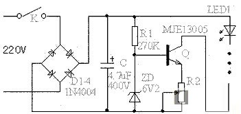
LEDs are widely used in the industry because of their wide application and reasonable price. Whether it is a festive decorative lamp or a variety of lamps used in the home, LED driving circuits are used because of its reduced energy consumption and long-term stable operation. Today I will introduce the LED lighting driver circuit from a practical LED circuit. Light-emitting diodes (LEDs) have become an alternative to today's lighting technology due to their high efficiency, energy saving, long life and environmental protection, and are gradually being applied to lighting. A key factor driving attention to LED lighting technology is that it greatly reduces energy consumption and enables long-term, reliable work. This article begins with a circuit using a constant current source. The main component transistor in this circuit requires a high-power tube with a withstand voltage of 400V or more and a power of 10W or more, such as MJE13003, MJE13005, etc., and a heat sink is required. The filter capacitor C has a capacity of 4.7uF and a withstand voltage of 400V or more. The current of the arc tube is determined by the R2 adjustment. For the convenience of adjustment, the variable resistor can be adjusted and then replaced with a fixed resistor of the same resistance. This circuit can be equipped with an arc tube. The number is less than a dozen, and the maximum can reach more than 90. Although the cost is increased, the effect is much better than that of the resistor-only current circuit. Even if the voltage fluctuates greatly, the circuit can keep the current constant. This is very advantageous for the life of the arc tube, and the current in this range can be kept substantially constant. The number of light-emitting tubes used in this circuit is not too small, and the less the efficiency, the lower the efficiency. The total power consumption of this circuit is about 6W. Here, I will tell you about the LED adoption and connection method or the serial connection method? The LEDs are connected in parallel or in series, and should be determined mainly according to the form and requirements of the power box circuit. With a series connection circuit, when one of the LEDs is open, the entire string of LEDs is not bright; but when one of the LEDs is shorted, the other LEDs are still bright. With the circuit of the parallel connection method, when one of the LEDs is open, the other LEDs can be bright; but when one of the LEDs is short-circuited, the power of the entire circuit will be short-circuited, so that not only other LEDs can not work normally, and It is also possible to damage the power supply. Therefore, the circuit connected in series is more advantageous. The parallel method only needs to apply a lower voltage across each LED, but it is necessary to use a ballast resistor or current source to ensure that the brightness of each LED is consistent. If the magnitude of the bias current flowing through each LED is different, their brightness is also different, resulting in uneven brightness of the entire light source. However, using ballast resistors or current sources to ensure consistent LED brightness will shorten battery life. The series connection method is very good in ensuring the consistency of the current flowing through each LED, but the power supply voltage is required to be high. When the LED adopts the parallel connection method, since the total current of the circuit is the sum of the respective LED currents, the power supply is required to supply a sufficiently large current. In fact, in parallel, the parallel or series connection has its advantages and disadvantages. You need to consider many factors in practical terms. In practical applications, LED arrays formed in series and parallel are often used, which can overcome or reduce the above-mentioned single LED open circuit or short circuit, causing the entire string of LEDs to be off or affecting the entire circuit and power supply. The so-called series-parallel is to use a small number of LEDs in series and then a series of ballast resistors to form a branch, and then several branches are connected in parallel to form a "branch group." In addition, it can also adopt the serial-parallel string form, that is, on the basis of the formed "branch group", a plurality of "branch groups" are connected in series to form the entire lamp circuit, and this connection not only reduces the failure of one LED. The influence surface, and the resistance of the ballast is reduced to zero, and several high-power resistors are turned into dozens of small power resistors, which are changed from centralized installation to distributed installation, which not only facilitates heat dissipation but also designs the lamps. compact. ZhenHuan`s Iron case junction box led drivers is constant voltage switch mode with UL/CUL and ETL/cETLclass 2 rated for indoor led lighting. The series led power drivers accepts universal input voltage 120VAC or 220VAC and designed to meet 0-10V/TRIAC/Phase-cut dimmable and non-dimmable led drivers with junction box. High power factor up to 0.95 and efficiency of 90% allows the driver to operate at low temperatures. 5 Years Warranty and OEM services can be acceptable. Iron Case Junction Box Led Driver UL Listed Led Lighting Drivers,Magnetic Low Voltage Lighting Drivers,Led Driver Switch,Transformers Last Light,Transformer Company near me Shenzhenshi Zhenhuan Electronic Co Ltd , https://www.szzhpower.com