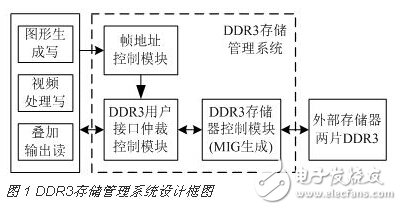
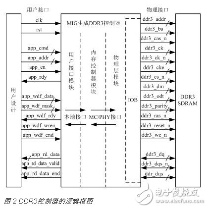
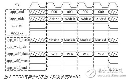
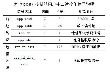
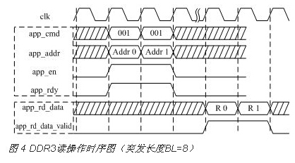
The on-board video graphics display system mainly realizes the drawing of 2D graphics, which constitutes various flight parameter images, and superimposes real-time scenery video. Because FPGA has powerful logic resources and rich IP cores, FPGA-based embedded system architecture is an ideal architectural choice for airborne video graphics display systems. Video processing and graphics generation need to store a large amount of data, and the internal storage resources of the FPGA cannot meet the storage requirements, so external memory needs to be configured. Compared with DDR2 SDRAM, DDR3 SDRAM has better bandwidth, faster transfer rate and more power saving, which can meet the requirements of large throughput and low power consumption. Therefore, DDR3 SDRAM is chosen as the external memory of the on-board video graphics display system. This paper designs and implements DDR3 multi-port storage management of FPGA-based video graphics display system with Kintex-7 series XC7K410T FPGA chip and two MT41J128M16 DDR3 SDRAM chips as hardware platforms. 1 Overall architecture design In the on-board video graphics display system, in order to achieve multi-port read and write access to DDR3, the designed DDR3 storage management system is shown in Figure 1. It mainly includes DDR3 memory control module, DDR3 user interface arbitration control module and frame address control module. The DDR3 memory control module adopts the MIG (Memory Interface Generator) scheme to establish the internal control logic of the FPGA to the DDR3 connection through the user interface. The user does not need to manage complicated control logic such as DDR3 initialization and register configuration, and only needs to control the read and write operations of the user interface. . The DDR3 user interface arbitration control module sets each data read and write request as an interrupt, and learns the arbitration control by borrowing the interrupt processing idea to solve the data storage conflict. The frame address control module controls the switching of the frame address. In order to improve the speed of parallel processing and simplify data read and write conflicts, graphics data and video data are stored in different DDR3s. 2 DDR3 memory control module design The logic block diagram of the DDR3 controller generated by MIG is shown in Figure 2. The DDR3 read and write operations can be completed only through the user interface signal, which greatly simplifies the design complexity of DDR3. 2.1 DDR3 control module user interface write operation design The DDR3 memory control module user interface write operation has two sets of systems, one is the address system, and the other is the data system. The user interface write operation signal description is shown in Table 1. The contents of the address system are app_addr and app_cmd, which are aligned and bound. When app_cmd is 000, it is a write command. When app_rdy (DDR3 control) and app_en (user control) are simultaneously raised, app_addr and app_cmd are written to the corresponding FIFO. The content of the data system is app_wdf_data, which stores write data to the write FIFO when app_wdf_rdy (DDR3 control) and app_wdf_wren (user control) are simultaneously pulled high. In order to simplify the design, the user interface write operation timing designed in this paper is shown in Figure 3, so that the two systems are completely aligned in timing. 2.2 DDR3 control module user interface read operation design User interface read operations are also divided into address systems and data systems. The user interface read operation signal description is shown in Table 2. The address system is the same as the write operation. On the rising edge of the clock and when app_rdy is high, the user port simultaneously issues a read command (app_cmd=001) and a read address, and pulls app_en high, writing the read command and address to the FIFO. For the data system, when app_rd_data_valid is valid, the read data is valid, and the read data sequence is the same as the address/control bus request command. The read operation address system and data system are generally not aligned. Because the address system sends to DDR3, DDR3 needs a certain reaction time. The read operation timing is shown in Figure 4.
The initial design of indoor fixed installation Led Display Screen mainly designs the size and model of the screen body according to the site conditions. The screen body size can be designed as 16:9, 2:1 or 4:3, etc. if the scene requirements are relatively long, multi screen display or screen cutting display can be designed. The screen model is generally based on the closest distance between the front row audience and the screen. Generally, the product of what model is used for the distance of how many meters, such as pH4 for the distance of 4 meters, pH2 for the distance of 2 meters, etc. Such a choice is also the most cost-effective.
Indoor Fixed LED Display features:
1. The screen body is not only reliable for wall installation, with a thickness of 7cm, beautiful and generous appearance, but also flush with the decorative surface to achieve the integration of screen and wall;
2. Light weight, only 10kg per square meter, suitable for any wall installation;
3. The Led Display adopts magnetic absorption structure, front and back maintenance, fast and safe;
4. For the same wall, choose a variety of models. According to the needs of customers, you can choose products with small spacing of P4, P3, P2 and above.
5. The cost is low, because there is no need to move, so the case structure is not needed, which greatly saves the cost of the box;
6. Various installation methods, including wall type, hanging installation, vertical installation, inlay installation, cantilever installation, etc. are selected according to the scene. Each installation method corresponds to different designers.
7. Different use scenarios can be used in one side, two sides, three sides or even more.
Application scenario: large airport, hospital, hotel, banquet hall, 4S shop, sales office, etc.
Screen structure: indoor fixed installation screen adopts high-strength magnetic absorption structure, with good front heat dissipation effect, no fan structure, no noise. Screen frame can be selected according to customer's requirements, such as black titanium, rose gold and so on. The inner part of the screen has been assembled with wire, and the outer part only needs to be connected with network cable and power cable.
Precautions: the screen body is not waterproof, and it can prevent sharp things from bumping.
Led Display Screen,Indoor Fixed Led Display,Indoor Fixed Led Display Screen,Indoor Fixed Led Wall Shenzhen Vision Display Technology Co,.LTD , https://www.ledvdi.com