Connector 2.5Mm Pitch,S11 Connectors,Welding Bar Connectors,Pressure Weld Bar Connector YUEQING WEIMAI ELECTRONICS CO.,LTD , https://www.wmconnector.com
The 74LS138 is a 3-to-8 line decoder belonging to the TTL (Transistor-Transistor Logic) family, specifically part of the 74 series. It has three input terminals labeled A0, A1, and A2, with A2 being the most significant bit. When the active high enable input (S1) is set to high, and the other two enable inputs (/S2 and /S3) are low, the binary value at the address inputs (A0, A1, A2) will be decoded into a low-level output on one of the eight output lines Y0 through Y7. For example, if A2A1A0 = 110, then Y6 will go low. The device typically operates at a 5V supply voltage.
The 74LS138 can be used in various applications. First, it can decode binary addresses and produce corresponding low-level outputs. Second, by cascading multiple 74LS138 chips, it can expand into a 24-line or even a 32-line decoder when an external inverter is used. Third, if one of the enable pins is used as a data input, the chip can function as a data distributor. Lastly, it is commonly used in memory expansion circuits for systems like the Intel 8086 processor.
In digital display applications, the 74LS138 acts as a decoder that activates specific segments of a seven-segment display based on the input code. Decoders like this are essential in combinatorial logic circuits and can be categorized into two main types: variable decoding and display decoding. Variable decoding involves converting a smaller number of input signals into a larger number of output signals, such as in binary-to-decimal or BCD decoding. Display decoding, on the other hand, is used to convert binary numbers into visual representations on LED or LCD displays.
The 74LS138 is widely used in digital electronics for tasks such as selecting memory addresses, controlling output devices, and managing signal routing. Its versatility makes it a popular choice in both educational projects and industrial applications.
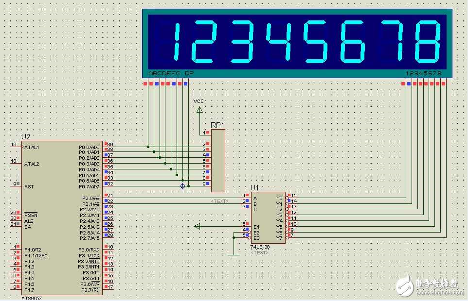
Below is a schematic diagram showing how the 74LS138 is used to drive a digital tube display:
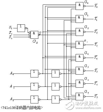
Here is a detailed circuit diagram illustrating the connection between the 74LS138 and the digital display:
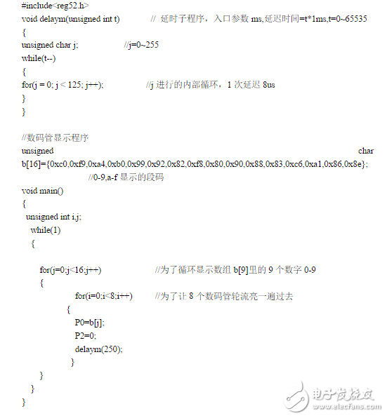
Additionally, here is a sample program demonstrating how the 74LS138 can be used to control an 8-digit digital display:
If you're interested in exploring more about the 74LS138 and its use in driving digital tubes, you can download the full circuit diagrams and programs for free. This resource includes everything needed to build and test a working 8-digit digital display system using the 74LS138 decoder.