Brushed Dc Motor,Dc Brushed Motor,Brushed Rc Motors,High Torque Brushed Dc Motor Changzhou Sherry International Trading Co., Ltd. , https://www.sherry-motor.com
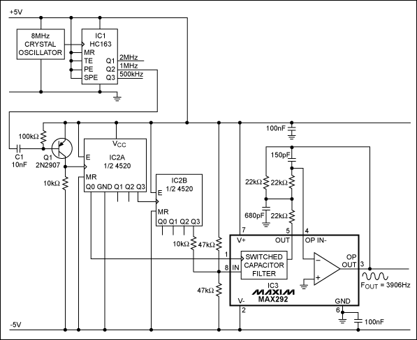
You can get greater accuracy and less drift by deriving the sine wave from a digital source. Because square waves includes a fundamental at the square-wave frequency plus an infinite number of odd harmonics, you can obtain the desired fundamental sinusoid by removing the harmonics with a lowpass filter. Switched-capacitor filters suit this applicaTIon (Figure 1). IC3 is an 8th-order, lowpass Butterworth type. 
Figure 1. Filtering the harmonics from a square wave produces a sinusoidal output whose stability and flexibility derive from digital circuitry.
The sine-wave generator starts with an 8MHz signal and divides it by eight to obtain 1MHz at C1. (IC1's 2MHz and 500kHz outputs can serve as alternate drive signals.) Q1 level-shifts the 1MHz pulses so they can drive the bipolar circuitry necessary for producing a bipolar output. (For unipolar outputs, you can operate the circuit on a single supply voltage by biasing the IC3 ground terminal to mid-rail and adding a decoupling capacitor.) Synchronous counter IC2 divides 1MHz by 256 to give the desired output frequency (3906Hz), and IC3 filters the harmonic frequencies.
The filter's clock is taken from the first divide-by-2 tap of IC2, to assure a 50% duty cycle. IC2 further divides this signal by 128 to assure that the filter's input signal (1MHz / 256) falls within the flat portion of the filter response. Fifty-percent duty cycles on the IC2 outputs assure a symmetrical sine-wave output. The filter's major pole, or corner frequency, is fixed with respect to the clock and forms an internal clock-to-corner ratio of 100: 1. Filter attenuation lowers the third-harmonic amplitude to -80dB.
Because the filter's input and clock frequencies have a fixed ratio of 1: 128, switching or sweeping the frequency applied at C1 has a proportional effect on the sine-wave generator output. Switching this frequency from 2MHz to 500kHz, for example, switches the output frequency from 7812Hz to 1953Hz. Output amplitude is not affected because this band is well below the smoothing filter's 25kHz corner frequency. Alias ​​frequencies are not a problem, because the frequencies that represent a potential cause of aliasing in this circuit—the odd-numbered harmonics that exceed half the clock rate—have insignificant amplitudes.
A related idea appeared in the July 25, 1994 issue of Electronic Design.
Servos, test equipment, and telecommunicaTIons systems are among the applicaTIons that require stable, frequency-accurate sine-wave sources. Many such sine-wave oscillators are available, but finding one with a saTIsfactory level of absolute accuracy and drift can be a problem.