The use of a series connection essentially guarantees current consistency, but requires a higher voltage to be applied to the LED string. To achieve proper illumination, a conventional white LED requires a 3.6V bias voltage and a bias current of up to 20mA. Figure 1 shows a low-cost inductive boost circuit that can adjust the brightness of seven white LED strings. This circuit can be divided into two parts: a boost circuit consisting of Q1 and Q2, and a control circuit consisting of Q3 and JFET1. Assuming Q1 is off, when the battery voltage is slightly higher than the VVB of Q2, the base of Q2 will flow a positive current (iB = (battery voltage VBE) / RJET1). At this time, Q2 is turned on, and the inductor L1 is grounded. As the current on L1 increases at di/dt, the energy is preserved in the L1 magnetic field. As the current gradually increases, it also flows through the resistor RSAT of Q2 (SD1 and the LED string are in an off state). The collector voltage of Q2 is high enough to turn Q1 on. The base voltage of Q1 is connected to the collector of Q2 through a feedforward network consisting of R1 and C1. R1 is also used to limit the base current of Q1. After Q1 is turned on, the base of the driving Q2 is grounded, so that Q2 is turned off, and the energy of L1 is released into the LED string as the magnetic field is weakened. The fast zero return action of L1 imposes a forward bias voltage higher than 26V on the LED string, causing the LED to emit white light. Since the human eye does not feel the high frequency flicker of the LED, the circuit can provide illumination with constant brightness. When L1 discharge ends, Q1 returns to the off state. During normal operation, this self-oscillating action is repeated until the battery voltage drops to a sum of VBE less than Q2 and the JFET1 voltage drop (approximately 1V), at which point Q2 is no longer conducting. The RSAT of L1 and Q2 and the switching characteristics of Q1 and Q2 also affect the oscillation period and duty cycle. The voltage of the battery pack (4 alkaline batteries) is increased above 26V to provide forward bias to the LED string consisting of 7 white LEDs in series. Q3 is biased by a small DC current (less than 20uA) flowing through R4 to regulate the channel resistance of JFET1 to regulate battery leakage current to extend battery life. The gate voltage of JFET1 is about 0.9V higher than the battery pack voltage. Here the p-JFET is used as a depletion mode device, and when VGS is equal to zero, the p-JFET is turned on. The source of the ET is connected to the battery terminal. The design engineer can turn off the channel by increasing the gate voltage (higher than the positive battery voltage). The higher the gate voltage is than the battery voltage, the greater the channel resistance. Therefore, when the battery pack voltage drops from 6V to 3V, the oscillation frequency decreases (the VGS of JFET1 will change slightly). At this time, the brightness of the LED slightly decreases. Ideally, the control loop will keep the LED current constant. However, the sensitivity of the human eye to light obeys the quasi-logarithmic relationship, so a small linear decrease in brightness is not easily noticeable until the battery voltage drops to about 2V. Another solution is to keep the output power of the battery (the product of current and voltage) constant. Because of the internal resistance loss of the battery, although this can keep the brightness of the LED unchanged, it will shorten the battery life, and the complexity of the circuit will be greatly improved. In summary, the LED brightness of this simple circuit will vary little over the life of the battery. The brightness of the LED string can be slightly adjusted. For example, the design engineer can adjust the manufacturing deviation of the triode and the LED by slightly changing the resistance of R2, so that the light output (unit: lumen) can be set to a fixed value. When the battery pack energy is about to be exhausted, the dimmed LED string can be short-circuited, and only one LED is connected. At this time, as long as the battery pack has a residual voltage of 1V, the LED can emit strong light. This single LED connection provides the ultimate emergency illumination with a waste battery. For safety reasons, all batteries must match when using alkaline batteries. When the energy of the battery with the least energy in the battery pack is completely exhausted, and the other battery has sufficient energy to reverse bias the energy-depleted battery, it will cause the energy-depleted battery to overheat and leak the milky acid, thereby generating safe question. In order to achieve battery matching, it is important to replace all four batteries at the same time with new batteries in the same package. The four AA alkaline batteries are rated at 4 x 1000 mAh, which means that the LEDs can be illuminated continuously for about 61 hours. The test results of the circuit prototype show that the continuous illumination time is a little more than two days (48 hours). Customized Metal Products series include all products which are designed and customerized produced accordingly to client's requirement or customer's diagram. Customized Metal Products Metal Drawer,Medical Cart,Metal Tool Box,Metal Network Box Foshan Dinghan Electrical Technology Co., Ltd , https://www.dinghanelectrical.com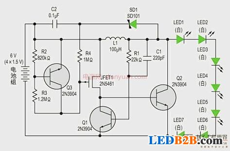
The article describes that in order to drive more than one high-brightness white LED , the design engineer needs to choose whether to connect the LEDs in series or to connect the LEDs in parallel . Parallel connections require only a low voltage across each LED, but ballast resistors or current sources are required to ensure uniform brightness for each LED. If the magnitude of the bias current flowing through each LED is different, their brightness is also different, resulting in uneven brightness of the entire light source. However, using ballast resistors or current sources to ensure consistent LED brightness will shorten battery life.