**HY-350N Welding Machine User Manual**
**1. Front Panel Components (See Table 1 for Detailed Parts)**
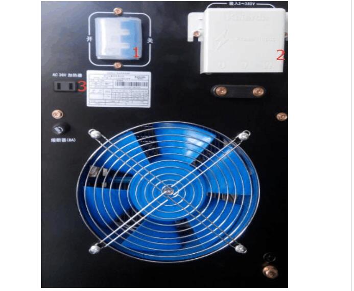
 **Wiring Details:**
- Connect the 380V Power Cable.
- Locate and use the start switch.
- Ensure the COâ‚‚ heater is properly connected.
**Control Cabinet Manual**
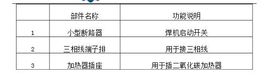
**1. Power On and Off Procedures (See Figure 1 for Front Panel Icons)**
**Wiring Details:**
- Connect the 380V Power Cable.
- Locate and use the start switch.
- Ensure the COâ‚‚ heater is properly connected.
**Control Cabinet Manual**
**1. Power On and Off Procedures (See Figure 1 for Front Panel Icons)**
 **1.1 Power On Steps:**
- Turn the main panel switch to "ON." The "CRP Power" indicator light should illuminate, indicating that the CRP controller is powered.
- Rotate the rear key switch to "ON." Press the "Start Power" button. You should hear the AC contactor engage, and the power indicator lights up, confirming full power to the electrical cabinet.
**1.2 Power Off Steps:**
- Rotate the key switch to "OFF." You will hear the AC contactor disconnect, and the power indicator will turn off.
- Turn the panel switch to "OFF" to completely cut off the power supply. The panel switch is the main power switch for the electrical cabinet.
**1.3 Emergency Stop Button Usage:**
- In an emergency or if the robot poses a threat to personnel, press the emergency stop button immediately. This will cut power to the electrical cabinet and stop the robot instantly.
- Do not use the emergency stop button in non-emergency situations, as it may cause damage to the structure or servo motors.
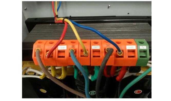
**2. Transformer Wiring Instructions:**
- Connect the transformer's input to a three-phase 380V (±10%) power supply.
- Ensure the power supply is balanced and not out of phase, as this can lead to unpredictable robot behavior.
- Always verify the wiring before powering up the system. (See diagram below)
**1.1 Power On Steps:**
- Turn the main panel switch to "ON." The "CRP Power" indicator light should illuminate, indicating that the CRP controller is powered.
- Rotate the rear key switch to "ON." Press the "Start Power" button. You should hear the AC contactor engage, and the power indicator lights up, confirming full power to the electrical cabinet.
**1.2 Power Off Steps:**
- Rotate the key switch to "OFF." You will hear the AC contactor disconnect, and the power indicator will turn off.
- Turn the panel switch to "OFF" to completely cut off the power supply. The panel switch is the main power switch for the electrical cabinet.
**1.3 Emergency Stop Button Usage:**
- In an emergency or if the robot poses a threat to personnel, press the emergency stop button immediately. This will cut power to the electrical cabinet and stop the robot instantly.
- Do not use the emergency stop button in non-emergency situations, as it may cause damage to the structure or servo motors.
**2. Transformer Wiring Instructions:**
- Connect the transformer's input to a three-phase 380V (±10%) power supply.
- Ensure the power supply is balanced and not out of phase, as this can lead to unpredictable robot behavior.
- Always verify the wiring before powering up the system. (See diagram below)
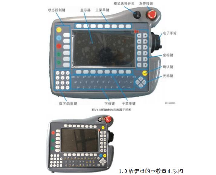
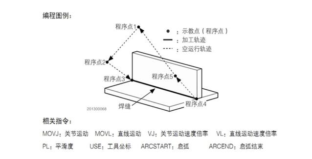
 **CRP Teach Pendant Quick Guide**
**1. Button Functions:**
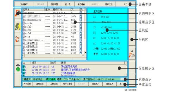
Each button on the teach pendant has a specific function. Refer to the image below for a clear visual guide to understand how to operate the CRP effectively. This helps users remember the steps more easily and improves overall efficiency.
**CRP Teach Pendant Quick Guide**
**1. Button Functions:**
Each button on the teach pendant has a specific function. Refer to the image below for a clear visual guide to understand how to operate the CRP effectively. This helps users remember the steps more easily and improves overall efficiency.
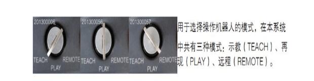
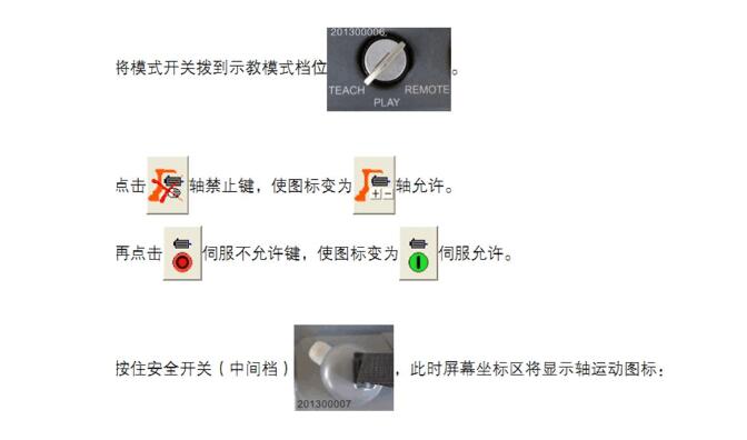
 **2. Mode Selection:**
Use the mode selection buttons to switch between different operational modes such as manual, automatic, or programming.
**2. Mode Selection:**
Use the mode selection buttons to switch between different operational modes such as manual, automatic, or programming.
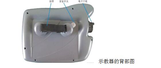
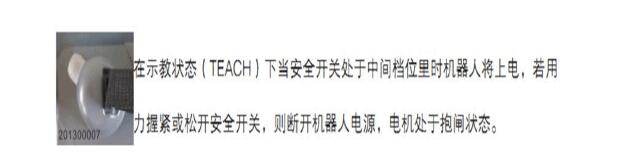
 **3. Safety Switch Instructions:**
The safety switch must be engaged during all operations to ensure the robot stops immediately if needed.
**3. Safety Switch Instructions:**
The safety switch must be engaged during all operations to ensure the robot stops immediately if needed.
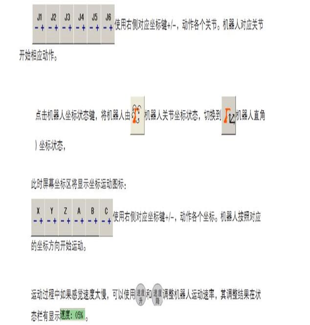
 **4. Manual Joint and Coordinate Control:**
Learn how to move the robot joints manually and adjust its coordinate system for precise positioning.
**4. Manual Joint and Coordinate Control:**
Learn how to move the robot joints manually and adjust its coordinate system for precise positioning.
 **5. Manual Teaching and Running the Robot:**
Follow these steps to manually teach and run the robot. This allows you to program the robot’s movements step by step.
**5. Manual Teaching and Running the Robot:**
Follow these steps to manually teach and run the robot. This allows you to program the robot’s movements step by step.
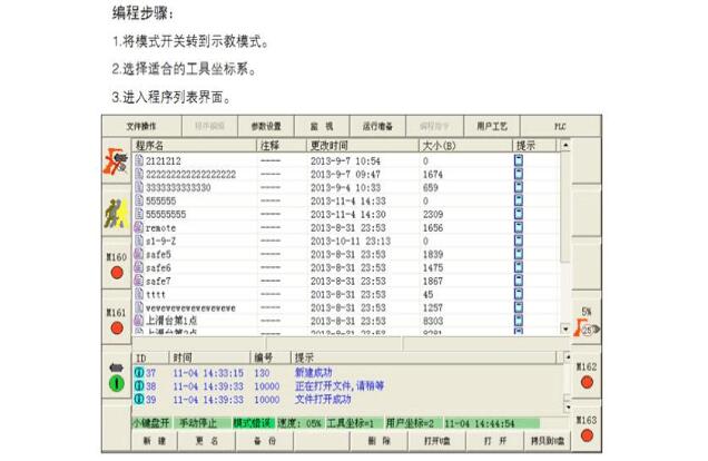
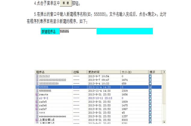
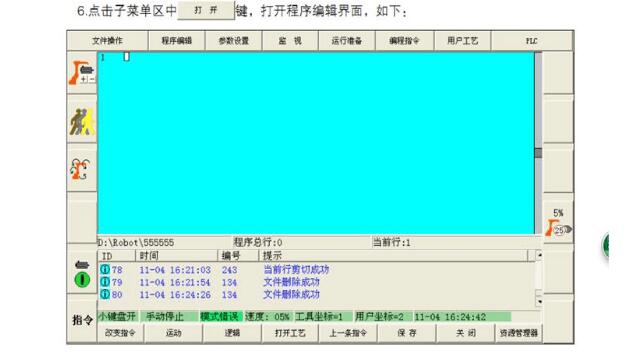
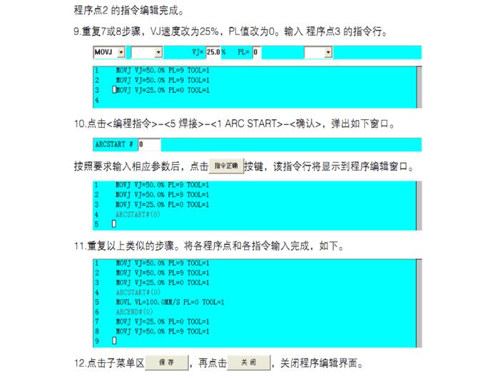
 **6. Teaching Programming Steps:**
This section provides a step-by-step guide on how to create and edit programs using the teach pendant.
**6. Teaching Programming Steps:**
This section provides a step-by-step guide on how to create and edit programs using the teach pendant.
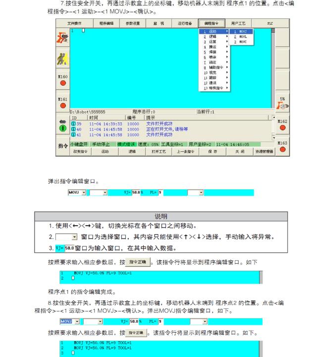
 **7. Program Execution**
(1) Set the key switch to "Play" and adjust the machine speed to 5% for slow operation. Make sure the emergency stop is accessible. Observe if the robot arm moves according to the programmed path. If not, stop it immediately.
(2) If the movement is correct, gradually increase the speed to the desired level.
This comprehensive manual ensures safe and efficient operation of the HY-350N welding machine and related systems. Always follow the instructions carefully to prevent accidents and ensure optimal performance.
**7. Program Execution**
(1) Set the key switch to "Play" and adjust the machine speed to 5% for slow operation. Make sure the emergency stop is accessible. Observe if the robot arm moves according to the programmed path. If not, stop it immediately.
(2) If the movement is correct, gradually increase the speed to the desired level.
This comprehensive manual ensures safe and efficient operation of the HY-350N welding machine and related systems. Always follow the instructions carefully to prevent accidents and ensure optimal performance.
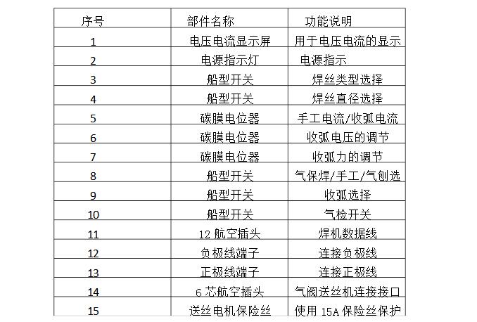
Table 1
**Wiring Instructions:** Connect the 12-pin aviation plug female of the welding machine to the 12-pin aviation plug male of the control cabinet. Ensure that the positive and negative wires are connected to the 13th and 12th terminals, respectively, as shown in the diagram above. Additionally, connect the 6-core aviation plug male of the welder to the corresponding female connector on the robot. **Gas Inspection:** Set the toggle switch 10 to position "1" for gas inspection. If the welding gun head releases gas, it indicates that the system is functioning properly. **Welding Settings:** - Toggle switch 3: Set to "0" for solid wire mode. - Toggle switch 4: Set to "0" for a 1.0 mm welding wire setting. - Toggle switch 8: Set to "1" for gas-shielded welding. - Toggle switch 9: Set to "1" for arc welding. - Toggle switch 10: Set to "0" for arc welding and welding file operation. **2. Rear Panel Components**Female header always called as [Header connector", YYE provide widely range of header connector, from 2.54mm (.100″ inch) pitch to 1.0mm (.039″ inch) pitch. The number of pins (contacts) is from 2 to 40 pins per orw. There are three type: Straight (Dip Vertical), Right angle, SMT (surface mount).
If you can not find the items you interest from above items, welcome to contact us, and you will always get fully responsive from us.
1.0mm Female Header
Dongguan City Yuanyue Electronics Co.Ltd , https://www.yyeconn.com