**What is Output Impedance?**
Impedance refers to the opposition a circuit or device offers to the flow of current. Specifically, output impedance is the resistance measured at the output terminal of a circuit or component. The lower the output impedance, the better the ability to drive heavier loads.
Output impedance represents the internal impedance of a voltage source (Thevenin equivalent) or a current source (Norton equivalent) at the output port of an independent power network. It is calculated as the impedance seen from the output port when all independent sources are turned off. This concept is crucial in understanding how a source interacts with its load.
**Output Impedance and Input Impedance**
While input impedance relates to what the circuit sees at its input, output impedance is about what the circuit provides at its output. In practical terms, output impedance is the effective resistance that the source presents to the load. It determines how well the source can maintain its output voltage or current under varying load conditions.
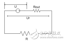
**Voltage Source Driven Circuit**
When a voltage source is connected to a load, it not only delivers energy to the load but also experiences some losses due to its internal resistance. For example, consider a constant voltage source U with an internal resistance Rout. When connected to a load R, the current flowing through the circuit is I = U / (R + Rout), and the voltage across the load becomes Ur = I × R = U × R / (R + Rout). The power delivered to the load is P = Ur × I = U² × R / (R + Rout)². From this, we can see that a lower output impedance allows for more efficient power transfer to the load.
A diagram illustrating the relationship between output impedance and load capacity is shown below:
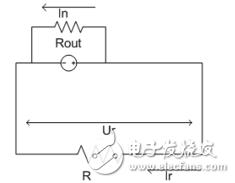
**Current Source Driven Circuit**
In a current source-driven circuit, the output impedance is typically represented as a resistor in parallel with the ideal current source. The current source provides a constant current I, which splits between the internal resistance Rout and the load R. The voltage across the load is Ur = I × (R × Rout) / (R + Rout), and the power delivered to the load is P = (I² × R²) / (R + Rout)². Maximum power is transferred when the load resistance matches the internal resistance of the source.
Another image showing the behavior of a current source is provided below:
**What is Load Capacity?**
Load capacity refers to the ability of a device to supply sufficient current or voltage to its connected load without significant degradation. For instance, in standard TTL circuits, the output high-level current is 0.4 mA, while the input high-level current required is only 0.04 mA. This means one standard TTL output can drive up to eight similar inputs.
Load capacity can also be thought of as the ability of a circuit to maintain its output voltage or current despite the presence of an external load. If the output voltage remains stable when a load is connected, the device has good load capacity. Similarly, if the output current meets the load’s requirements, the system is considered to have adequate load capability.
**Output Impedance vs. Load Capacity**
Output impedance is essentially the internal resistance of a signal source. An ideal voltage source would have zero internal resistance, while an ideal current source would have infinite output impedance. However, real-world sources have non-zero internal resistances that affect their performance.
For a voltage source, the internal resistance causes a voltage drop when current flows through the load. This limits the maximum power that can be delivered. For a current source, the output impedance is in parallel with the source, and higher output impedance means less impact on the load.
To better understand load capacity, think of it like the strength of a driver. A weak driver may only be able to push a small load, such as a light bulb, while a strong driver can handle larger loads, like a motor or speaker.
According to the voltage divider rule, the voltage across a load depends on the ratio of its resistance to the total resistance in the circuit. A lower output impedance means less voltage is lost across the source itself, allowing more voltage to reach the load. This makes amplifiers with lower output impedance more efficient in delivering power.
In general, voltage sources should have low output impedance, while current sources should have high output impedance. However, in high-frequency applications, impedance matching becomes important. Additionally, current limiting is often necessary to protect both the source and the load.
A typical example of a high-power amplifier uses MOSFETs because of their low internal resistance, which allows more power to be delivered to the load efficiently.
Friction Disc
The Friction Disc is a kind of Printer Accessories.
The cartridge is irradiated by laser beam to adsorb toner, and then the toner is hot pressed by fixing roller for printing. In this process, there will be part of toner residual, which can not be "granules returned to the warehouse"; Automatic cleaning function is not adsorbed new toner particles and directly print, will remain toner away, fully ensure the next printing effect. And the Plate-Grid plays an important role. When high voltage generator to a high voltage electrode, wire electrode with reseau formed between a strong electric field, and release the corona, wire electrode and the photosensitive drum ionizes the air between the air ions migrate to the drum surface, make the photoconductor (drum) surface is full of charge, so can spare toner "adsorption to warehouse", so as to save toner, The purpose of reducing environmental pollution.
High Accuracy Friction Disc,Semi-Etching Surface Friction Disc,Drive Shaft Parts ,Printer Friction Disc
SHAOXING HUALI ELECTRONICS CO., LTD. , https://www.cnsxhuali.com