Lightning surge is a common issue in power systems, particularly affecting switching power supplies. It occurs due to various factors such as direct or indirect lightning strikes, which can generate high voltage and current surges that may damage electronic components. Understanding the causes of lightning surge is essential for designing effective protection mechanisms.
**Causes of Lightning Surge**
1) **Lightning Strikes (Mainly Indirect):** When lightning strikes outdoor lines, it generates a large amount of current that flows into external lines or grounding resistors, creating interference voltages. Indirect lightning strikes between clouds or within clouds can induce voltage or current on the lines. Additionally, when lightning hits nearby objects, it creates an electromagnetic field. As outdoor lines pass through this field, they can experience induced voltage and current. Similarly, if lightning hits the surrounding ground, the ground current can be introduced through the common grounding system, causing interference.
2) **Switching Transients:** These are sudden changes in voltage or current caused by switching operations in the power system. Examples include the switching of compensation capacitor groups, large switches near the device, thyristor devices with resonant lines, and various systemic faults like short circuits or arcing faults between equipment grounding networks or grounded systems.
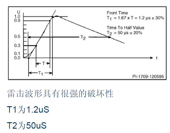
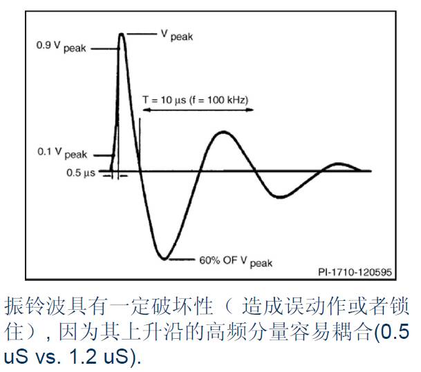
Although switching power supplies are designed to withstand lightning surges, two common types of surges—“lightning strike†and “ringing†waves—can still cause damage. The following diagrams illustrate these phenomena and their effects on power supplies.
**Basic Protection Devices for Lightning Surge**
Several devices are used to protect against lightning surges:
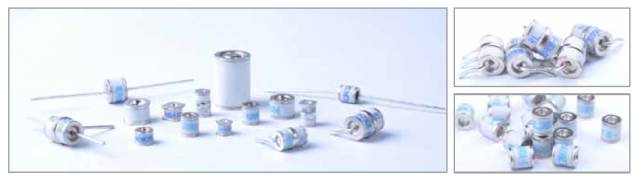
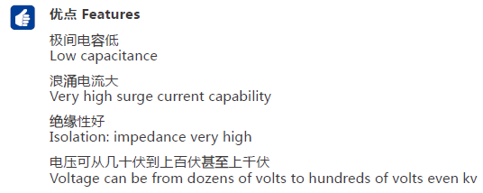
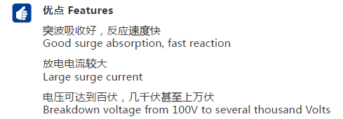
- **GDT (Gas Discharge Tube):** A voltage-conducting switching device used in parallel between the line and the ground. It has a high surge current capacity and low interelectrode capacitance, making it ideal for lightning protection.
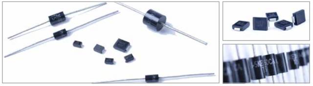
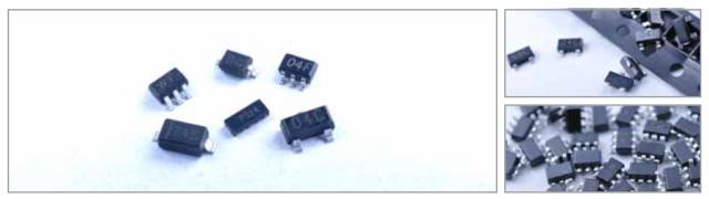
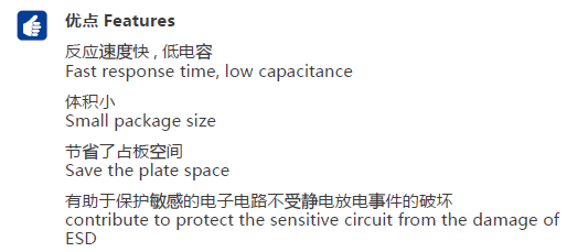
- **TVS (Transient Voltage Suppressor) Diode:** A voltage-limiting overvoltage protection device that responds quickly to limit excessive voltage to a safe range, protecting the downstream circuit.
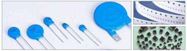
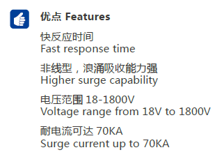
- **MOV (Metal Oxide Varistor):** A semiconductor voltage-limiting surge device made from zinc oxide. It is widely used in electronic circuits due to its nonlinear characteristics and superior surge absorption capability.
- **PTC (Positive Temperature Coefficient) Self-Recovering Fuse:** An overcurrent protection component that increases resistance when overheated, effectively limiting current flow.
- **ESD/TVS Arrays:** These provide fast response times, low on-voltage, and multiple data line protection, making them suitable for high-frequency applications.
- **Glass Discharge Tube:** An overvoltage protection device that suppresses high voltage pulses and protects low-voltage circuits from damage. It offers fast response, impact resistance, and long life.
**Lightning Surge Test Items and PCB Layout Considerations**
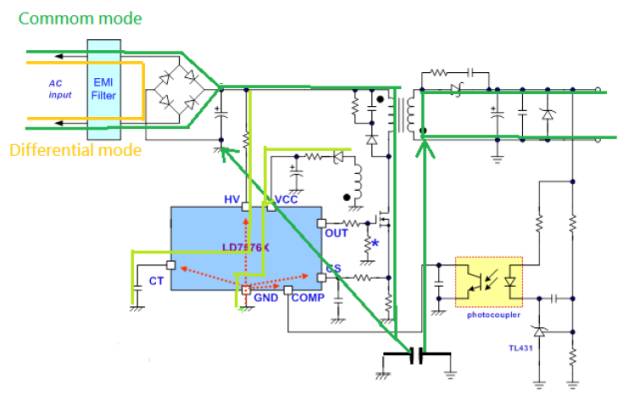
Lightning tests typically involve different combinations of power (L), neutral (N), and earth (E). The main test items include L→E, N→E, L&N→E, and L→N. These tests are categorized into Common Mode and Differential Mode.
- **Common Mode Tests (L→E, N→E, L&N→E):** These tests evaluate the ability of the system to handle surges that appear simultaneously on both lines relative to ground.
- **Differential Mode Test (L→N):** This test evaluates the ability of the system to handle surges that appear between the live and neutral lines.
The layout of the PCB plays a critical role in ensuring effective lightning surge protection. Key considerations include:
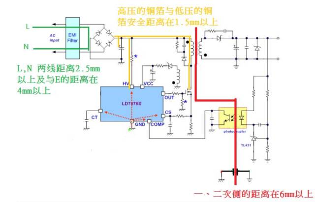
- **Transformer Safety Distance:** Ensuring sufficient spacing between primary and secondary components to prevent breakdown.
- **Photocoupler Placement:** Avoiding traces beneath the component to maintain safety distances.
- **Y-Cap Layout:** Proper placement to avoid energy bleed paths that could damage sensitive components.
For differential mode surges, protective components like MOVs, thermistors, and spark gaps are used to absorb and suppress energy. For common mode surges, the focus is on isolating the primary and secondary sides and ensuring proper grounding.
**Grounding Practices**
Proper grounding is crucial for lightning protection. On the primary side, the layout should prioritize the sequence of large capacitors and ground connections. On the secondary side, the ground of the TL431 should be connected to the output capacitor, and the Y-cap’s ground should connect to the transformer's ground.
**High-Voltage Layout Considerations**
- The distance between L and N lines should be at least 2.5mm, and the distance from E should be 4mm or more.
- High-voltage copper foil and low-voltage copper foil should have a safe distance of at least 1.5mm.
- The distance between the primary and secondary sides should be above 6mm.
**PWM IC Layout Tips**
PWM ICs are vulnerable components, so careful layout is essential. Capacitors should be placed close to the IC to prevent transient voltages from entering. Grounding should be done in a single point to minimize noise.
**Typical Lightning Test Specifications**
- **No Malfunction:** 4 kV / 12 Ω common mode, 2 kV / 2 Ω differential mode
- **Can Be Restarted:** 6 kV / 12 Ω common mode, 4 kV / 2 Ω differential mode
Lightning surges can be either differential mode or common mode, with peak voltages reaching the kilovolt level. Input impedance and short-circuit current are also specified, such as 6 kV / 12 Ω = 500A.
**Damage Caused by Lightning Strikes**
- **Differential Mode Surges:** Can cause high voltage increases in input bulk capacitors and damage input components.
- **Common Mode Surges:** May cause arcing, leading to high-frequency currents that couple into low-voltage circuits and cause malfunctions.
**Additional Tips**
- Prevent arcing by increasing spatial distance or slotting the PCB.
- If a varistor is easily damaged, use a shrink sleeve and place it away from the fuse.
- Ensure correct connection of varistors to minimize parasitic inductance.
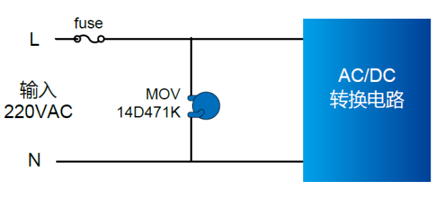
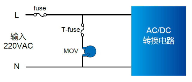
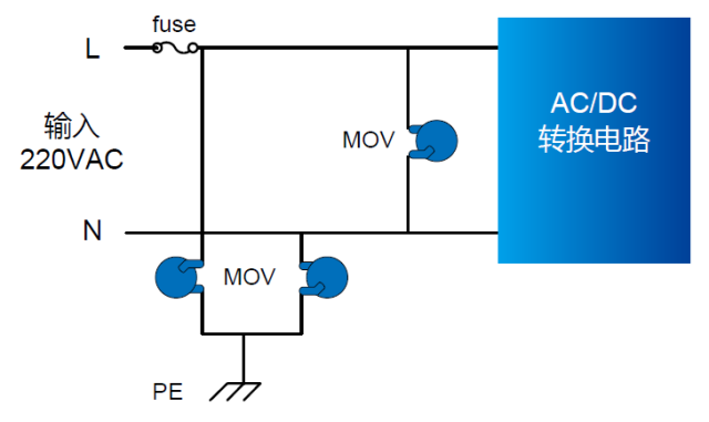
**LED Drive Power Lightning Surge Design**
For LED drive power supplies, especially those not grounded, common protection methods include using fuses and MOVs to protect against overvoltage. Adding a temperature fuse or ceramic gas discharge tube can further enhance protection.
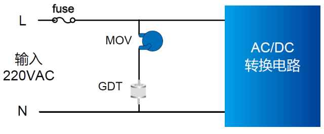
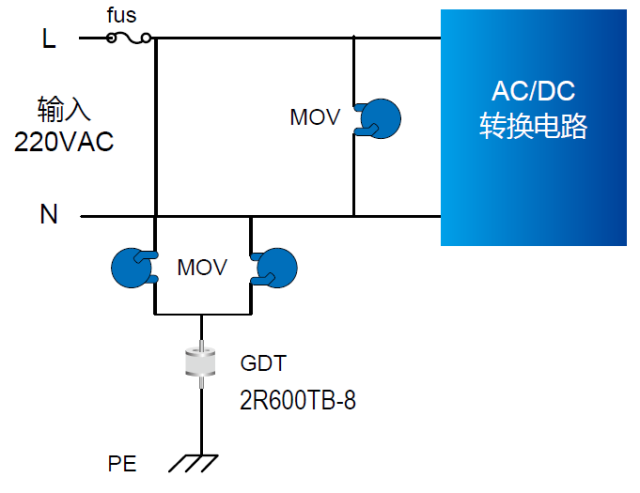
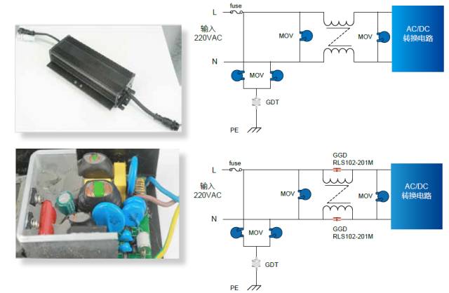
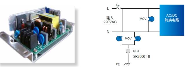
For grounded power supplies, additional protection measures such as GDTs and MOVs are used to handle higher surge requirements. Proper selection of discharge tubes ensures compliance with Hi-Pot and surge test standards.
Single Axis Solar Tracker System
Single Axis Solar Tracker System price,Sun System Powered One Axis,One Axis Solar Tracker Single Axis,Mounting System Solar Tracker
Hebei Jinbiao Construction Materials Tech Corp., Ltd. , https://www.pvcarportsystem.com