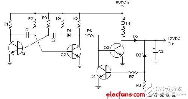
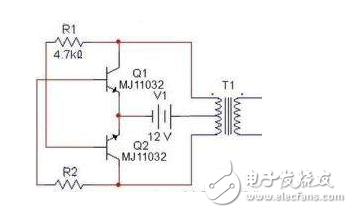
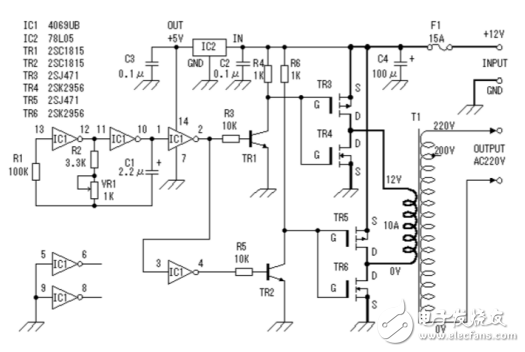
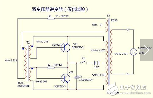
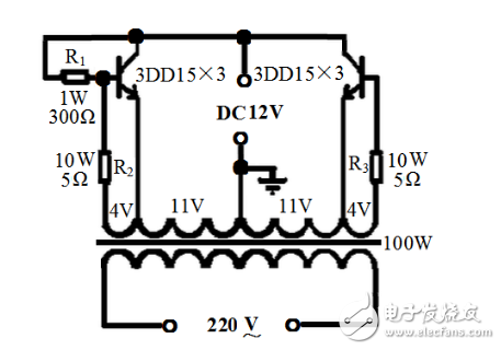
This circuit is designed to generate extremely high voltage, and it should be handled with extreme caution to avoid electric shock. The circuit uses a transformer that can output over 1000V, combined with an 8-stage voltage doubler, which can boost the voltage up to 20,000V DC. It’s important to note that working with such high voltages requires proper insulation, safety measures, and experience in electronics. Always ensure that the circuit is properly isolated and never touch any exposed components when it's powered on. This circuit is a simple design that converts 6V to 12V and can deliver up to 800mA of current at 12V. It’s ideal for basic applications like motorcycle audio systems or small power supplies. The output voltage can be adjusted by replacing some components in the circuit, making it flexible for different needs. However, it's not recommended for high-power or sensitive devices due to its limited capacity. As shown in the diagram, this circuit includes a transformer for boosting voltage, along with a rectangular wave circuit. The transformer T1 is used for step-up, while V1 provides the power supply. Resistors R1 and R2 are typically between 1.2kΩ and 4.7kΩ, and the choice of transistor depends on the transformer’s capacity. If the transformer has a larger capacity, a higher-power transistor may be required. In this example, a 0V-12V-12V transformer, a Darlington transistor MJ11032, and 4.7kΩ resistors were used. The circuit can deliver around 100W of output power, but the transformer must be selected carefully to match the desired performance. This inverter circuit is built using a MOSFET and a standard power transformer. The output power depends on the power rating of both the MOSFET and the transformer. A higher-rated MOSFET and transformer will allow for greater output power, making this circuit suitable for small to medium power applications. It’s commonly used in portable inverters or low-power AC devices. In this circuit, the transformer windings are labeled as 25T, 310T, 20T, and 250T. VT1 is a high-power transistor, often used in TV power supplies. R1 is a 15–50Ω, 5W resistor, while R4 is a 470Ω, 3W resistor. This configuration allows for efficient conversion from DC to AC, though careful component selection is essential to ensure stability and safety. This circuit uses a 100W control transformer, with the secondary coil removed and rewound. The number of turns per volt is calculated, and the secondary coil is rewound with φ1.35mm enameled wire. A 22V main coil is wound first, with a mid-tap, followed by two 4V feedback coils made with φ0.47mm wire. Insulation between layers is done with kraft paper. After assembly, the core is reinserted, and the 4V coils are connected to the main coil in reverse polarity. If the voltage increases after connection, the wiring is correct. Resistors R2 and R3 are connected in series with the 4V coil and are made from resistance wire. Their value is chosen based on the output power, typically several ohms. A 1W, 300Ω bias resistor is used. The transistors are three 3DD15s connected in parallel. After connecting the circuit, check for errors and test with a 100W bulb. If the bulb doesn’t light, adjust the base resistance until it works. Finally, connect it to a TV to see if it starts properly. Automatic Light Curtain,Laser Light Curtain,Automation Light Beam Sensor,Automatic Infrared Beam Sensor,Infrared Beam Curttain Sensor,Infrared Beam Sensor Jining Keli Photoelectronic Industrial Co.,Ltd , https://www.sdkelien.com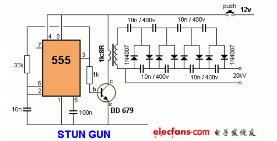
**12V Boost to 20000V Circuit Diagram (1)**
This Automation curtain is specially designed for automation industry. SDKELI LSC2 light curtain is designed for automation field, with small size, compact structure and strong anti-interference ability, and the product meets IEC 61496-2 standards. The automatic light curtain is with reliable quality and very competitive price. It has been used in many factories.