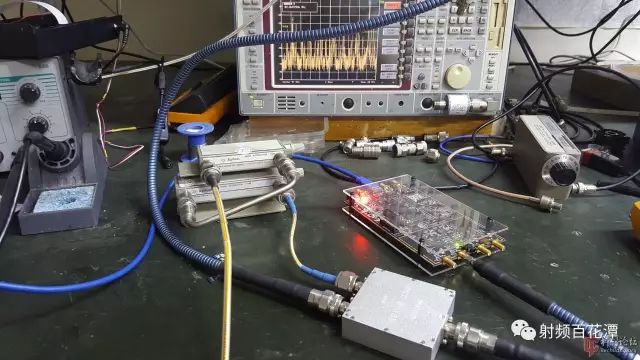
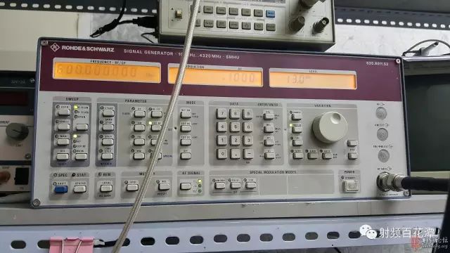
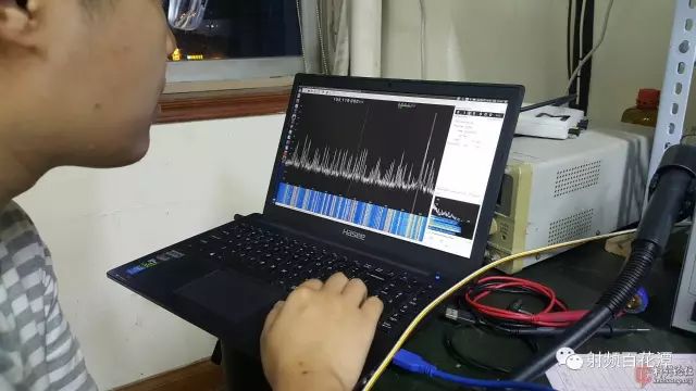
In narrowband applications, zero-IF software-defined radio chips have gained significant popularity, with the Analog Devices AD9361 being a prime example. Here, "narrowband" refers to systems that operate within a relatively limited frequency range, such as 700–1200 MHz. However, when it comes to broadband applications—like handheld broadband receivers—the required frequency coverage can span from 50 MHz to 6 GHz. In such a wide range, what kind of performance can be expected without complex pre-selection filtering? I once heard a senior engineer describe it as a mess, full of pitfalls. It's not only prone to failure but also generates many false signals, which made me hesitant. As a result, I opted for traditional multi-conversion superheterodyne architectures combined with digital downconversion (DDC) for more reliable performance. After all, in instrument-level applications, the zero-IF approach was often looked down upon. Recently, we needed to develop a broadband product, and due to cost constraints, I decided to personally test whether the zero-IF approach is truly as problematic as some experts claimed. If it works well, it could save us a lot of effort and time. This post is based on my own testing using the AD9361 to explore some basic performance characteristics of zero-IF receivers. My knowledge is limited, so the content isn't highly technical—it’s more of a casual discussion. Feel free to comment, correct, or even criticize. I'm open to feedback. The first parameter I tested was the receiver’s blocking performance, which is one of the most concerning aspects for me. Test Procedure: Definition: A receiver is receiving a signal at frequency A, while a strong interference at frequency B (outside the desired band) also enters the system. When the strength of this interference causes the receiver’s ability to detect the signal at A to drop by 6 dB, the power level of the interfering signal is considered the blocking level of the receiver. The outdoor antenna connects to the AD9361 through a mechanical attenuator and a combiner. A strong signal source is also connected via the same combiner. The output level of the strong signal is gradually increased until the AD9361 becomes blocked. The board used is a B210-compatible unit from BA3CE. Due to losses in the combiner and cables, the actual signal strength entering the test board was calibrated before the test. If multiple frequencies are tested, recalibration is necessary each time. While the AD9361 has internal amplitude calibration, it’s quite accurate. Since the sensitivity loss is a relative measurement, the absolute power level measured by the AD9361 doesn’t need to be calibrated. Equipment Needed: Step attenuator, signal source, spectrum analyzer or test receiver, combiner, and necessary cables. The spectrum analyzer is used to verify the strength of the interfering signal reaching the test board. No formal photos were taken during the test, just a few quick shots. Here’s the setup: the white thick cable is the combiner. A blue coaxial cable from above is the signal source, and the golden cable connected to the outdoor antenna is the attenuator. Still using the same signal source. An SDR software is used to display the spectrum. Warmonkey is running the software. Test Results: 1. With the outdoor antenna connected and no attenuation, the AD9361 is clearly overloaded regardless of the frequency set in the software. There’s a lot of noise and false signals. This is understandable in a city center near a radio station. 2. When 20dB of attenuation is applied, the overload is eliminated. The B210 doesn’t trigger any built-in overload alarms from the AD9361, so manual judgment is required. The method involves increasing the attenuation and checking if the signal strength decreases proportionally. 3. When the B210 is set to receive FM broadcast, injecting an interference of -2dBm at any frequency below 3GHz causes a 6dB drop in the received signal strength. At this point, the gain was already at its minimum, and there was no preamplifier. Increasing the gain would likely worsen the blocking performance, though this wasn’t tested thoroughly. 4. Whether the signal is weak or strong, the reduction trend under interference is consistent. 5. The noise floor of the B210 is around -105dBm under the same settings. Interpretation of Results: In simple terms, if you inject an interference signal into the receiving port that reaches -2dBm, the sensitivity of the AD9361 will drop by 6dB. Without a preselector, it’s very easy to get blocked. In fact, -2dBm is actually a decent value. The FFT graph still maintains a dynamic range of about 90dB (nearly 100dB, slightly compressed), which shows good performance. Although there are some shortcomings, it’s not as bad as I had imagined. Netizen Comment: It seems like the dynamic range of a regular triode. It’s awkward to not add a bandpass filter. Since traditional analog reception is still widely used, it might be possible to develop a universal receiver module. For example, detection modules, AGC modules, 455kHz IF modules, 10.7MHz IF modules, high-IF modules, mixer modules, etc. Such development is straightforward, and a receiver can be built quickly. Standardized modules make it easier to control specifications, and they could even be sold to hobbyists. Schrödinger’s Cat: Module-based design was common in devices 30 years ago. Today, modern devices are highly integrated and low-power. These modules are usually replaced by ICs, but complex wiring and system simulations are still required, making it less cost-effective for product-level applications. Chips like the AD9361 integrate everything into a single chip, and all functions can be controlled via software. The development environment and open-source code are mature, making them advantageous for general RF applications. Adding a few peripherals with some clever design techniques can expand functionality and frequency range at a low cost.
High
purity Tin wire is a special target material, Vacuum coating target technology
was used in Automobile glass.
Pure Tin Wire,Tin Wire,Tin Solder Wire,Tin Plated Copper Wire Shaoxing Tianlong Tin Materials Co.,Ltd. , https://www.tianlongspray.com