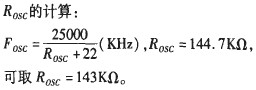
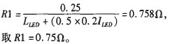
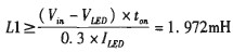
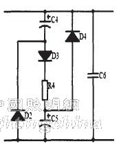
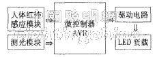
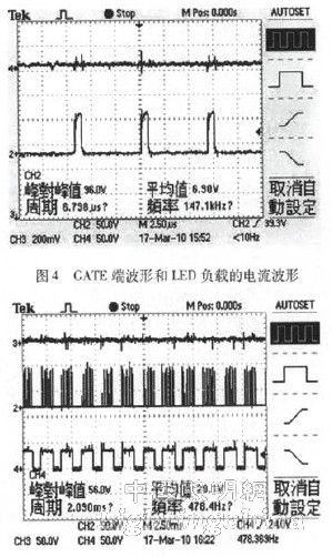
1 Introduction With the breakthrough of key technologies for LED component quality and conversion efficiency, industry experts believe that LED will become the mainstream of lighting in the next three to five years. Replacing incandescent or fluorescent lamps with LEDs is environmentally friendly and non-polluting. It is safe and reliable to use and easy to maintain. The LED is a non-linear device. When the LED is turned on, the current will increase a lot as long as the voltage on the LED is slightly larger. Therefore, even a small change in voltage can greatly affect the operation of the LED device, causing excessive current or even heat damage. Constant current source drive is the best way to drive LEDs. Driven by a constant current source, the current flowing through the LED will not be affected by voltage and ambient temperature changes, as well as the discreteness of the LED parameters, so that the current can be kept constant and the various excellent characteristics of the LED can be fully utilized. 2J. In order to save electricity and reduce the impact on the power quality of the power grid, it is also required that its drive circuit must have high efficiency and power factor, and it requires that the harmonic current injected into the power grid is small, and the cost is low, the volume is small, and the weight is light. . The intelligent dimming part is an indispensable part of LED lighting, and it is also a development trend of LED lighting driver. In order to meet the above requirements, this solution uses a high-power constant current driver chip SMD802 and a microcontroller ATMEGAl6. 2 drive circuit introduction LED lights can only be powered by DC. When using mains supply, there is an AC/DC converter between the mains and the LEDs. The main components are filtering and protection circuits, rectifiers, passive PFC and DC/DC conversion. The rectifier circuit can be implemented by a diode rectifier bridge, wherein the DC/DC converter is implemented by a high-power constant current driving chip SMD802. SMD802 is a low-cost, high-efficiency control chip with step-down, step-up, buck-boost, and efficiency of more than 90%. It is especially suitable for driving multiple strings of LEDs or LED arrays. The chip is suitable for both global AC input and 8V to 450V DC input. In the case of AC input, in order to improve the work factor, the passive power factor correction circuit can be easily added to the line when the input power is less than 25 W through the limitation of the AC harmonics of the illumination device specified by EN61000-3-2 ClassC. achieve. SMD802 can meet the requirements of different loads (any number in series). The output constant current drive current can be set from tens of milliamps to 1 amp. It is suitable for high-power LED applications with multiple series connections, and the output power is also several tens of watts. The operating frequency (switching frequency) can be set by the user and the frequency range is from 25KHz to 300KHz. It can be dimmed in analog mode or dimmed by input low frequency PWM signal (50Hz~1000Hz). Internal undervoltage lockout protection and overload protection. 2.1 How the drive works Before introducing the principle of the workpiece of the driver, we will introduce the pins of the SMD802 chip. The driver chip has three kinds of pin packages. The functions of each pin are as follows: VIN: Input voltage 8V ~ 450VDC. CS: current sampling input of LED string GND: chip ground GATE: drive the gate of the external MOSFET PWM_D: Low-frequency PWM dimming pin, also an enable input pin. Internally integrate 100kIl pull-down resistor to ground VDD: Internal linear power supply (typically 7.5V). Capable of supplying up to 1mA to external lines. When the AC input voltage is near zero crossing, a large enough storage capacitor is used to provide energy. LD: Linear dimmer is used to change the current limit threshold for current sampling comparison Rosc: Frequency oscillation controller. A resistor is connected between this pin and ground to set the frequency of the PWM. The designed driver circuit diagram is shown in Figure l(a). The circuit is very simple and the components are few. The working principle is as follows: (1) When the GATE terminal outputs a high level, the current flow of the driving circuit is as shown in Fig. 1(a). Inductor L1 is in the charging state, the current of the inductor L1 increases, the voltage of the two ends of the sampling resistor R1 increases, and is connected to the CS terminal of the SMD802 through RC filtering, when the voltage of the two ends of the sampling resistor R1 is greater than 250 mA (before the experiment, the chip is performed on the chip) The measured value is 269mV), and the GATE output of the chip SMD802 is low, thereby turning off the N-channel MOS transistor. (2) When the output of the GATE terminal is low, the MOS transistor is quickly turned off, and the current flow of the driving circuit is as shown in Fig. 1(b). The current of the LED lamp is continuously flowed through the inductor L1 and the freewheeling diode D1, so that the current flows. The current of the LED lamp is in continuous mode. C2 and R2 play the role of eliminating interference, R3 and ZDl take the role of limiting voltage regulation, and C1 has a certain improvement effect on the ripple of the LED lamp side. Figure 1 drive circuit working state 2.2 Parameter design Here we mainly design the parameters of some key components, and other components can be selected and designed according to the SMD802 document. The LED lamp used here is 22W, which consists of a row of lamps connected in series with a current of 0.3A and a voltage of 66V. The operating frequency of the SMD802 is 150KHz. Calculation of the sampling resistor R1: Calculation of the inductance LI: Vin is the voltage after rectification and considers that the city has 10% change of electricity. ton is the time when the switch is turned on. The inductance Ll is 2.5mH ​​and the saturation current is lA. N-channel MOS tube selection: VDss=1.25 Vin=1.25X342.2 V=428V, the current is more than 3 times that of Iled. The MOS tube used in this scheme is 4N60 (withstand voltage 600V, rated current is 4A). Selection of freewheeling diode Dl: Refer to MOS tube selection. The freewheeling diode used in this scheme is MURl60 (withstand voltage 600V, rated current is 1A), and the reverse recovery time is as short as possible. 3 passive PFC When the load power is less than 25W, passive PFC can be used to improve the power factor of the circuit. The passive PFC circuit used in this experiment is a valley filling circuit, as shown in Figure 2. The valley fill circuits (D2, D3, D4, C4, C5, and R4) limit the 3rd and 5th harmonic values ​​of the power frequency current, providing excellent power factor correction (usually 0.9 or higher), used by C6 Suppress high frequency interference signals. The relevant parameters are designed as: 1N4007 for diodes, 22uF for two electrolytic capacitors, 250V for electrolytic capacitors, resistor R4 for 10Q, I/2W resistors, capacitor C6 for 0.022uf Film capacitor with 400V resistance. Figure 2 Passive PFC circuit 4 intelligent control module dimming The core of the intelligent module is the microcontroller. This experiment uses the ATMEGAl6 microcontroller. The cost performance of the AVR is much higher than that of the 51 MCU: high speed, using the RISC instruction set: the main frequency is up to 20MHz; low power consumption, wide voltage: 3.3V-5.5 V, minimum full-speed operation power consumption <300uA; IO drive capability: push-pull current capability up to 30mA, can directly drive buzzer, relay, etc.; on-chip resources are rich: external interrupt, timer / counter, UART, SPI, 12C, ADC, analog comparator. The power supply requirement of the MCU is 3.3v~5.5V. Because the power supply required by the MCU is very small, it can be realized by a power frequency transformer, rectifier bridge and a linear regulated power supply circuit, which will not affect the efficiency of the whole circuit. The peripheral modules mainly include a human body infrared sensing module and a photometric module, and the intelligent control module is composed as shown in FIG. Figure 3 Intelligent Control Module The human body infrared sensing module uses CD-HW01. The function of the module is: when the person enters the sensing range (generally set to 3m), the output is high. When the person leaves the sensing range, the automatic delay is turned off and the output is low. Flat, realize the role of automatic switch. At the same time, it can be set to work during the day or when the light is strong. The metering module can use the TLS256I chip. The light intensity sensor TSL2561 is a high-speed, low-power, wide-range, programmable and flexible configuration light intensity digital conversion chip introduced by TAOS. The chip can be widely used in various types of display monitors. Under the lighting conditions, the display provides the best display brightness and minimizes power consumption. It can also be used in many occasions such as street lighting control and security lighting. The light intensity sensor used in the scheme is composed of a photoresistor and a resistor connected in series. When the light intensity is different, the voltage values ​​of the two ends of the photoresistor are different, and the voltage of the two ends of the photoresistor is converted by the A/D of the ATMEGAl6 single-chip microcomputer to obtain a voltage value. The timer is a timer ∞, using fast PWM mode, the MCU uses the internal 8M crystal oscillator, the output waveform frequency is 488Hz (because the self-contained crystal frequency accuracy is not high, the actual output waveform frequency has a certain error with 488Hz, can To meet the requirements of dimming), the value of the output comparison register OCR0 is controlled by the voltage value obtained by the A/D converter, thereby achieving the duty ratio of the PWM wave of the control output, thereby realizing the effect of dimming. 5 experimental data and graphics When the intelligent control module is not added, PWM-D terminal and LD, %. Connected together via a capacitor to ground. The GATE waveform of the SMD802 and the current waveform of the LED load are shown in Figure 4. Waveform 2 of Figure 4 is the waveform at the GATE end with a frequency of 147.1 kHz, which is consistent with the waveform of the theoretical analysis of the chip. Waveform 4 of Fig. 4 is the current waveform of the LED load, and the average current is 0.31 A. From the waveform, it can be seen that the constant current effect is good. The efficiency of the initial test circuit can reach 0.9. When adding the intelligent control module, the signal frequency of the PB3 output of the microcontroller ATMEGAl6 to the SMD802 PWM-D terminal is 478.4 Hz. In the SMD802 document, the signal input to the PWM-D terminal is required to be isolated, so the following processing is performed: the intelligent control module The ground is connected to the ground of the driver, and a diode is added between PB3 and PWM-D to isolate. The duty ratio is determined by the light intensity. The stronger the light intensity, the smaller the duty ratio. The waveform 4 of Fig. 5 is the waveform output to the PWM-D terminal, the frequency is 478.4 Hz, and the duty ratio is about 70%. Waveform 2 of Figure 5 is the GATE output waveform. Waveform 3 of Fig. 5 is the current waveform of the LED. Actually, the current waveform is composed of two parts of rising and falling. The performance in Fig. 5 is not clear, and the average current value is somewhat reduced. Figure 5 Adding the dimming PWM-D waveform, GATE waveform and LED load current waveform           6 Conclusion The circuit structure of the driving circuit is very simple. The design is convenient, and the components occupy a small volume. The efficiency of the circuit can reach above 09, which can fully reflect the energy saving advantages of LED. Adding the intelligent dimming control module, you can twilight according to the requirements, to achieve the protection of the LED and make people feel more comfortable. A passive PFC circuit is added. The power factor of the driver can be controlled to achieve a power factor of 0.9. However, flawless PFC has a fatal flaw. Electrolytic capacitors are used in the circuit. Since the life of the electrolytic battery is relatively short compared to the LED life, it cannot match the LED load. Therefore, replacing the electrolytic capacitor is the primary problem of LED development. To achieve this breakthrough, we can truly realize the advantages of LED energy saving, environmental protection and long life. Edit: Cedar
Class 180 thin insulation thickness of polyester -imide aluminum round wire
Packaging Details cartons for outer packing, reels with enameled wire inside, paper outside the reels. we also can pack the goods according to the requirements of the clients .
250*500/250*600/250*400 wooden spools.
Super Enamelled Copper Wire,Eiw Enameled Aluminium Wire,Eiw Polyesterimide Enameled Winding Wire,Round Enameled Aluminum Wire HENAN HUAYANG ELECTRICAL TECHNOLOGY GROUP CO.,LTD , https://www.huaonwire.com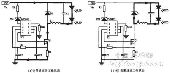
About Eiw Enameled Aluminium Wire
