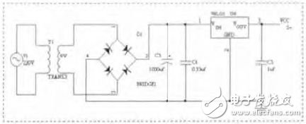
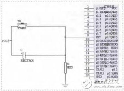
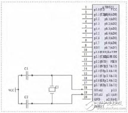
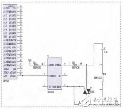
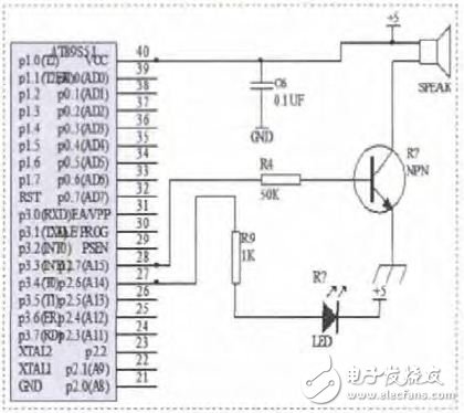
Temperature control technology not only plays a very important role in industrial production, but also plays a vital role in daily life. In this paper, the hardware and software design of the system is carried out. Based on the mathematical model of the temperature control system, the system controller is designed by analyzing the PID control, and the software and hardware debugging work of the system is completed. The algorithm is simple, reliable, and robust, and the PID controller parameters directly affect the control effect. 1. System Overview 1.1 Overall structure of the system The system uses the AT89S51's rich peripheral modules to build a hardware platform. The hardware circuit of the system includes: an analog part and a digital part, and the basic circuit is composed of a core processing module, a temperature collecting module, a keyboard display module and a control execution module. 1.2 System Workflow When the system starts working, the temperature reading command is first issued by the MCU control software, and the current temperature value of the controlled object is collected by the digital temperature sensor and sent to the display for real-time display. Then, the temperature measurement is compared with the set value T, and the difference is sent to the PID controller. After the PID controller processes, it outputs a certain amount of control amount, and is converted into an analog voltage amount by D/A, and controls the controlled object to perform heating. 1.3 System Software Design Method The whole system software design includes two parts: the management program and the control program. The management program includes the dynamic refresh of the LED display, the control indicator, and the scanning and response of the processing keyboard. The control program includes A/D conversion, median filtering, over-limit alarm processing, PID calculation, and the like. 2. System hardware structure 2.1 Power circuit design The DC power supply used in the system is provided by a series DC regulated power supply consisting of a three-terminal integrated voltage regulator. The design uses three three-terminal integrated voltage regulators, LM7805LM7815 and LM7915, to provide +5V DC voltage, and the output current is 1A. The transformer will step down the 220V mains and then rectify through the rectifier bridge to use large-capacity electrolytic capacitors. Filtering is performed to reduce the output voltage ripple. The power circuit diagram is shown in Figure 1. Figure 1 power circuit diagram 2.2 Reset circuit design The design of the reset circuit of the single chip directly affects the reliability of the whole system. Only a reliable reset circuit can prevent the system from "dead" and "program flying". The circuit diagram is shown in Figure 2. Figure 2 reset circuit diagram 2.3 Clock circuit design The controller adopts the internal oscillation mode to obtain the clock signal of the single chip microcomputer, and the clock signal obtained by this method is relatively stable. Figure 3 shows the clock circuit. Figure 3 clock circuit diagram 2.4 thyristor output circuit A thyristor is a power semiconductor device, referred to as SCR, also known as a thyristor. This part is a two-way thyristor drive circuit that controls the power of the electric heating furnace, and uses MOC3041 as the drive circuit. As shown in Figure 4. Figure 4 thyristor output circuit 2.5 sound and light alarm circuit module When the temperature measurement value of a channel exceeds the preset upper and lower limit alarm values ​​or the system operation fails, the system emits an audible and visual alarm to alert the user. As shown in Figure 5. Figure 5 sound and light alarm circuit diagram 3. System software design 3.1 System main program design In the reactor system, the main program's function is mainly to set the relevant variables used in the program execution process, allocate registers, initialize the required parameters, call the corresponding function modules according to the timer interrupt program, and complete certain tasks. Brushless DC Motor,DC Brushless Motor,24V DC Brushless Motor,High Torque Brushless Motor Changzhou Sherry International Trading Co., Ltd. , https://www.sherry-motor.com