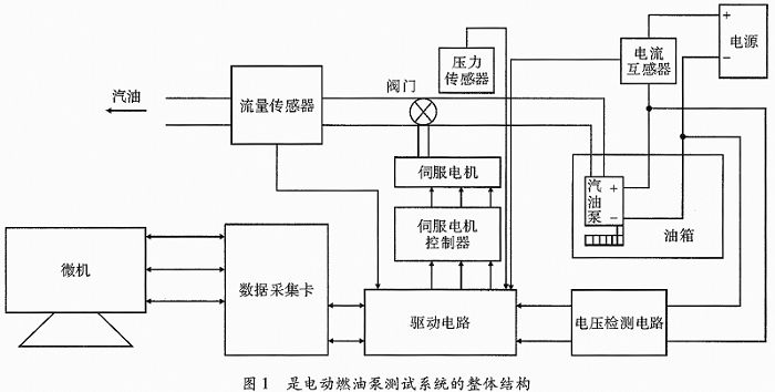
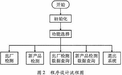
Abstract Aiming at the inconvenience of manual detection and operation of automobile electric fuel pump, data accuracy and low efficiency, a vehicle fuel pump was used as a research object to develop a vehicle electric fuel pump performance test system based on LabVIEW environment and data acquisition card. The system collects parameters such as fuel pressure, fuel flow, oil pump working voltage and working current through NI-USB 6210 data acquisition card, and realizes control parameter setting, oil pump performance evaluation, data display, storage and history with the upper computer interface compiled by LabVIEW. Record queries and other functions. The experimental results show that the test time of the system is shortened by more than 90% compared with the traditional detection method, and the test accuracy and detection efficiency of the fuel pump performance are greatly improved. This article refers to the address: http:// Key words data acquisition card; fuel pump; LabVIEW; performance evaluation The electric fuel pump is a key component in the fuel supply system of the automobile engine. Its function is to provide sufficient fuel pressure and flow to meet the fuel requirements of various engine conditions. The performance of the fuel pump directly affects the performance of the engine, so the fuel pump performance must be tested. At present, there are many types of domestic electric fuel pumps, but the performance detection technology is relatively backward, mainly using manual meter reading and vacuum method. The manual manual detection method has poor measurement accuracy, low efficiency, and low stability, and is not suitable for mass production testing of electric fuel pumps. The disadvantage of the vacuum method is that the fuel pump is easily damaged by overheating. Therefore, based on the shortcomings of the above two methods and the actual needs of domestic related enterprises, this paper designs an automatic performance detection system based on LabVIEW electric fuel pump. After functional verification, it realizes fast and high-precision detection and evaluation of electric fuel performance detection. Meet the actual needs of the company. 1 test system solution System components: As a graphical programming language, LabVIEW makes system functions easier to expand, more versatile, and more flexible. The electric fuel pump detection system is based on virtual instrument technology, with computer as the core, with graphical programming language and NI-USB 6210 data acquisition card. The system itself does not have any instrument panel, and uses the PC graphics environment to build a graphical virtual instrument. Panel, complete instrument control, data acquisition, data analysis and data display. According to the analysis, the electric fuel pump belongs to the object to be tested. The sensor is used to detect the outlet back pressure, working current and working flow. The oil pressure value of the oil pump is measured by the partial pressure method. The servo motor and other actuators are used to control the ball valve in the pipeline. The valve opening is used to adjust the outlet back pressure and flow rate. The data acquisition card has input and output functions, which can transfer data to the computer, and can also transmit computer instructions to the actuator; the computer is the core of the detection system. Based on the design idea of ​​virtual instrument, the test system of electric fuel pump is designed. Figure 1 is an overall structural view of an electric fuel pump test system. The automotive electric fuel pump performance detection system is developed based on the multi-function data acquisition card. It mainly tests the five parameters of the outlet back pressure, working flow, working current and pressure relief value of the oil pump under different working conditions, and then compares the standard values. The error between the measured value and the measured value is used to determine the quality of the electric fuel pump. 2 system hardware design The detection system mainly measures the flow of the oil circuit, the current and voltage of the fuel pump under different pressures in the fuel pipe. According to the functions realized by the system, the hardware includes the selection of sensors, the design of the conditioning circuit, the selection and control of the servo motor, and the design of the data acquisition card. 2.1 Sensor selection and conditioning circuit The role of sensors and transducers is to convert various physical signals into electrical signals that can be acquired by the DAQ system. The output signals of the sensor and the converter cannot be directly read by the acquisition device, and need to be amplified, filtered, isolated, etc., and then sent to the data acquisition device for data acquisition. The pressure sensor converts the physical quantity of the pressure signal into a standard current value signal. The test system uses CYB13 series isolated pressure transmitter, which has strong anti-interference ability and stable performance. The flow collection system converts the flow in the oil supply line into electrical pulses for output. This test system uses DiggesaFH type micro electromagnetic flowmeter. This flow meter counts 988 pulses and is 1 L flow, with high stability and high precision. The current acquisition system converts the amplified current into a small current value that the DAQ system can acquire. The test system uses RS-1212-14D1 DC current isolation transmitter, which can detect the DC current signal in isolation, small size, low power consumption and high precision. The voltage acquisition system measures through the principle of resistor division. A series circuit is formed by using a precision resistor of 10 kΩ and 20 kΩ. The series circuit and the oil pump form a parallel circuit, and the working voltage of the oil pump is measured by the principle of resistance voltage division. The signal conditioning circuit converts the current signal output by the sensor into a standard voltage signal of 0 to 5 V to be input to the data acquisition card, and also performs filtering and impurity removal processing. 2.2 Motor selection The detection system of the electric fuel pump of the automobile controls the stepping motor through the software program when the stepping motor is used to control the ball valve. When the pressure of the fuel pipe is adjusted to 0.3 MPa, the measured fuel pipe pressure cannot be accurately controlled at 0.3 MPa; In the process of controlling the ball valve, the motor will have a “lost step†phenomenon; the detection system is equipped with a servo motor, and the pressure of the fuel pipe is precisely controlled by a software program, and the stepping motor “lost step†phenomenon does not occur. The detection system selects a servo motor as the control motor of the detection system on the basis of comparing the stepper motor and the servo motor to control the fuel pipe. The servo motor is in the working principle of the detection system, and the motor controls the position and state of the ball valve. The motor receives one pulse by pulse positioning, and rotates the angle corresponding to one pulse to realize the rotation of the ball valve. The servo motor itself has the function of emitting a pulse, so every time the servo motor rotates by one angle, a corresponding number of pulses will be emitted to form a closed loop. Through the closed loop system, the specified pulse is sent to the servo motor, and the corresponding pulse is confirmed, so that the rotation of the motor can be accurately controlled, and the precise positioning of the ball valve in the fuel detection system is realized. 2.3 Data Acquisition Hardware Settings This part consists of computer hardware and a data acquisition card. The data collected by the data acquisition card NI USB 6210 is transmitted to the computer through the bus. The computer drives the software to the hardware through the writing of the driver and the application program. 3 system software design The software of the detection system is written in the graphical language LabVIEW. The modular software is used to divide the detection system into different modules. The main program calls different function modules through mode selection. The programming flow chart is shown in Figure 2. According to the user's needs, enter the program and select the corresponding module: (1) If the factory inspection module is selected, Figure 3 is the operation interface. Before starting the test, the parameters of each test point should be set. Select the corresponding product type to complete the parameter setting. If there is no relevant product parameter in the database, click Add New. The product can complete parameter settings and database updates. After the parameter setting is completed, click the Start Test button and the system will complete the test. If the test does not meet the requirements, you can retest, and the test results can be saved in an Excel spreadsheet. Multi Usb Charger,Usb Wall Charger,Fast Mobile Charger,Fast Car Charger Ninghai Yingjiao Electrical Co., Ltd. , https://www.yingjiaoadapters.com