Improper adjustment of the automotive power system can lead to frequent voltage dips and overshoots. Under normal conditions, the voltage range will be between 11 and 15 volts, and in the case of transient start and execution, it will be between 8 and 24 volts. Therefore, a voltage margin test must be performed when testing the engine control unit (ECU) to verify proper operation under extreme bias voltages and how much tolerance is allowed.
This article refers to the address: http://
In the highly competitive automotive electronics market, testing time is a matter of seconds. Testing at multiple bias voltage levels is a necessary but time consuming operation in ECU testing. Most system DC power supplies take a long time to change the new output settings and stabilize them, resulting in an increase in total test time. This article uses Agilent Technologies' N6700 modular power supply system and N6752A power supply module as an example to illustrate how to shorten the ECU test time and improve the performance of various functions.
ECU input and output characteristics
The ECU uses a number of signals to monitor the car and its environment to manage and control the engine and auxiliary equipment for optimal operation. Figure 1 summarizes the many input and output signals of a typical ECU.
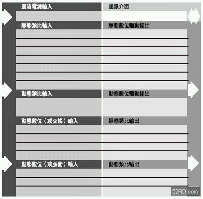
Figure 1: Many input and output signals of a typical ECU
In the functional test of the ECU, the correct test system resources will simulate various input signals in a controlled manner, and will load and check the output to get the correct response. Depending on the number of inputs and outputs, ECU testing clearly requires the use of vast test system resources.
Important bias voltage levels in automotive power systems
Depending on the operating state of the car, certain voltage levels are often encountered in the power system of the car. These levels will become important voltages for ECU testing, as shown in Figure 2. Some related tests performed under these important voltages include:
• Check continuity between multiple ground, power, and high current driver pins when the power supply is set to 0 or off.
• Apply a very low voltage and measure the resulting current to check for shorts or other unexpected errors.
• Various functional tests range from a low level of approximately 8 volts (representative start) to a high level of approximately 15 volts (representing full charge).
• If an ECU voltage monitoring circuit is included, it is usually verified or verified using at least two endpoint operating voltages.
• Verify the ECU's low voltage reset level by examining the minimum “must not trip†and the maximum “must trip†threshold.
During the test, the ECU may experience up to 20 changes in the bias voltage level.
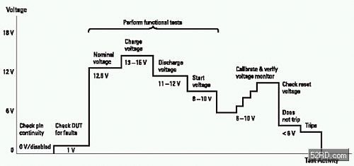
Figure 2: Some voltage levels in the vehicle's power system become important voltages for ECU testing
Power supply output response time
When changing the output voltage setting of the power supply to a new value, several steps must be taken, as shown in Figure 3. The time taken for these steps is limited. When the power supply receives an instruction, it must be processed, so there will be an instruction processing time. The output of the power supply will then respond and change to the new settings. The time it takes to reach the final value in a stable segment is the output response time. A 1% stable section is suitable for ECU testing. Of particular note is the output response time when the setting is lowered. Many power supplies must rely on real DUT loads to reduce the voltage. In the case of small loads, some power supplies that do not have a down-regulator can take up to a second to reach the final value. The N6752A power supply module has a built-in down-regulator that speeds up the set-down without being affected by the load. In the ECU test, both the up and down settings must be fast enough.
Use Agilent Technologies' N6700 Modular Power System and N6752A Power Supply Module to increase test speeds from slower power supplies to N6700 and N6752A, reducing test throughput and output Response time, multiplied by the number of conversions of the output voltage. The shortened 200 milliseconds multiplied by 15 output transitions yielded a total of 3 seconds of test time. In the case of an ECU test that takes 20 seconds, it is equivalent to a 15% increase in test speed. ECU manufacturers value this result because it helps reduce test costs and provide immediate benefits.
Related applications
• Automotive Electronic Control Module (ECM)
• Automotive body electronics
• Automotive Telematics
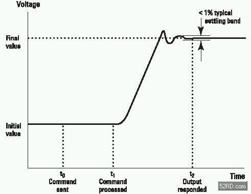
Figure 3. Command processing and output response of the power supply
PTFE Conveyor Belt is a kind of belt which is non-toxic, non-odor, non-stick surface and suitable for conveying food and food materials.The belt can be used in various power transmission applications, such as drying application, screen print dryers, shrink tunnels.
The belt are known for their long serving life and sturdy construction.
Properties:
·Exceptional strength and dimensional stability
·Operating temperature range from -70℃ to +260℃
·Excellent release properties.
·Low coefficient of friction.
·Easily cleaned.
·Good chemical, moisture and corrosion resistance.
·Good electrical insulation and di-electric properties.
·Food contact approval.


|
Standard Roll Size (mtrs): |
3800mm*250m |
|
mesh size (mm) |
1*1, 2*2, 2*2.5, 4*4, 10*10 |
(Other thickness available upon request)
Conveyor Belt
Conveyor Belt,Teflon Conveyor Belts,Fiberglass Open Mesh Conveyor Belt,Teflon Mesh Conveyor Belt
TAIZHOU YAXING PLASTIC INDUSTRY CO., LTD , https://www.yaxingptfe.com