 The problem of high line losses in power supply companies and distribution networks has always affected the economic benefits of power supply companies. In recent years, the level of grid equipment has been greatly improved, and the line loss rate has been declining year by year. However, the loss ratio of low-voltage lines in some Taiwan districts, especially in the densely populated areas of towns and villages, remains high, and the line loss in individual stations is as high as 30% or more. Enterprise line loss management and management have brought great pressure.
 The loss of the distribution network is divided into the management line loss and the technical line loss. The management line loss is reduced through scientific management methods. The technical line loss mainly adopts technical measures to reduce, including technical transformation of the grid and improvement of the grid operation mode. Let's talk about several technical measures for energy saving and loss reduction in rural distribution networks.
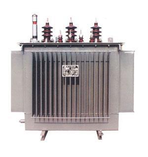
I. Reasonable selection of distribution transformers The distribution transformer selection includes the selection of the distribution transformer's capacity, model, and the location of the transformer's installation location.
1. Distribution Transformer Capacity Selection The distribution transformer capacity should be selected according to the current status and development trend of the area. If the capacity is selected too large, “big horse-drawn car†phenomenon will occur, the transformer utilization rate will be low, and the no-load loss will increase. If the selected capacity is too small, the transformer will be overloaded and the loss will increase. If it is serious, the transformer may be overheated or burned. Therefore, the distribution transformer must be reasonably selected according to the normal load and maximum load of the installed area.
2. The choice of the distribution transformer model is mainly the selection of new models of high-efficiency energy-saving distribution transformers that use new technologies, new materials, and new processes to reduce energy consumption. (1) Use amorphous alloy core transformer. Amorphous alloy core transformer is a transformer made of a new type of magnetically conductive material—amorphous alloy made of iron core. It reduces the no-load loss of iron core transformer by about 80% compared to silicon steel, and the no-load current drops by about 85%. It is a distribution transformer with ideal energy-saving effect. It is especially suitable for use in rural grids and places where the transformer load rate is low. Compared with S9 type distribution transformers, three-phase amorphous alloy core distribution transformers have considerable annual energy savings.
(2) Select a wound core fully sealed distribution transformer. Roll core sealed transformer is a new generation of low noise, low loss transformer developed in recent years. The coil core is seamless. All the magnetic flux is in the same direction as the silicon steel sheet, fully utilizing silicon steel. The orientation properties of the sheet, under the same conditions, compared with the laminated iron core, the no-load loss decreased by 7% to 10%, and the no-load current decreased by 50% to 70%. Because the transformer high and low voltage coils are continuously wound on the stem, the windings are tight and the concentricity is good, the anti-theft performance of the product is further enhanced, the noise is reduced by more than 10 decibels, and the temperature rise is low by 16 to 20K.
Because the no-load current of the transformer is small, the loss reduction effect is obvious, the network power factor can be increased, the input of the reactive power compensation equipment can be reduced, the equipment investment can be saved, and the operation energy consumption can be reduced.
(3) Select on-load automatic capacity distribution transformer. On-load auto-capacitance transformer is the transformer coils with string, parallel connection, in the transformer's low voltage coil connected with on-load capacity switch, in the transformer low-voltage side connected with current transformers and automatic controller, through the current transformer to provide the transformer In the load state, the automatic controller can automatically adjust the operation according to the load. On-load self-capacity transformer solves the long-term disadvantages of higher electromagnetic transformer winding loss and manual operation, which further reduces transformer no-load loss and no-load current. The on-load self-capacity transformer is especially suitable for users with load dispersion, seasonality, and low average load factor.
3. Selection of Distribution Transformer Installation Location In addition to meeting the site and environmental requirements, the transformer installation location must also be considered to be close to the center of the load distribution so that the power supply radius can be shortened as much as possible, preferably within 500 meters. For stations with relatively decentralized loads, most of the load should also be controlled within 500 meters.
Second, improve the structure of the low-voltage power supply network grid According to theoretical calculations, if the distribution transformer is located at the center of the load, the branch line radiates to the surrounding area. Under the condition that the total network resistance is equal and the power supply capacity is the same, the more low-voltage branch lines, the loss The smaller it is, the faster it falls with the square of the number of branch lines. Therefore, from the low-voltage outlet of the distribution transformer to each load point, the number of branch lines should be increased as much as possible, and the power supply radius should be controlled within 500 meters, which is conducive to reducing the low-voltage network loss. Third, the transformation of the old low-voltage metering device low-pressure metering device transformation, including metering, table boxes, in-out line transformation. One is to reduce the metering error; the second is to use a closed meter box, which can play a good anti-electricity stealing effect; the third is to eliminate the power loss caused by the broken wires and poor contact by replacing the inlet and outlet wires.
For example, if the two 10 kV lines of a certain power supply establishment of the author’s unit pass the transformation of residents’ measuring devices, the line loss is reduced from the original 20% to the current 7.5% to 8.5%, and the effect is significant.
Third, keep the transformer low-voltage three-phase load balance operation Distribution network transformer Y, yn0 wiring group transformer, when the three-phase load balance, the zero line no current. When the load increases (mainly the increase or decrease of single-phase equipment load), there will be three-phase load imbalance. When the three-phase load is unbalanced, there will be a zero-sequence current passing through the low-voltage winding and the secondary neutral line, thereby increasing the loss of the transformer. Therefore, adjusting the three-phase load of the distribution transformer has certain economic value.
In the low-voltage power network, due to the access of various single-phase loads, the three-phase load is often unbalanced, which will greatly increase the losses in transformers and low-voltage lines. In the case of the same power, the three-phase load is asymmetrical. The loss of transformers and lines is much higher than that of symmetrical operation. If the three-phase load current unbalance ratio is above 20%, the line loss rate can be increased by 2% to 3%. To obtain the balance of the three-phase load and reduce the line loss, the three-phase connection lines should be different from the same pole as far as possible. On the basis of the above, the load balance of the three-phase access lines is maintained; the transformer load balancing test is also carried out according to the characteristics of seasonal changes, and load adjustments are performed in time.
IV. Increasing Reactive Power Compensation The distribution network reactive power compensation can be divided into secondary variable concentration compensation, 10kV line dispersion compensation, transformer compensation and random compensation, among which the follower compensation is one of the most effective methods for reactive power on-site balancing. It is also an important measure for energy saving and loss reduction of the power supply branch.
First, install compensating capacitors on the substation 10kV busbar of the conditional installation centralized compensation device so that the reactive power is balanced. Second, using the reactive power compensation method with centralized compensation on the low-voltage side, partially balancing the reactive power of the distribution network on the one hand, on the other hand reducing the active loss and voltage loss, and on the other hand, to meet the needs of the lowest compensation when the load changes, avoiding light Load time over compensation.
Thirdly, a shunt capacitor should be installed on a 10kV line with a long line and a large load to perform decentralized compensation. The compensation capacity should be compensated by taking 1.1 to 1.3 times the total reactive power of the distribution transformer for no-load reactive power.
Fourth, increase the power users reactive power compensation, new power users in the design phase to take into account the reactive power compensation device; at this stage the reactive power compensation focus on small capacity power users, the compensation method should be based on random compensation The realization of reactive power on the spot balance, so you can receive a better effect of reducing losses, improve the utilization of distribution transformers.
For example: There are 458 overhead transformer bases in a branch company, all without reactive power compensation equipment. There are 567 distribution and distribution stations in the community, of which 388 have been installed with reactive power compensation cabinets and 231 of them have not been put into operation. According to the calculation of the maintenance cost of 1,000 yuan for each reactive compensation cabinet, the total amount of funds required for investing in the reactive compensation cabinets is 231 thousand yuan. According to the monthly reduction of 600kWh per reactive power compensation cabinet, the monthly savings of 69,300 yuan will be paid back within 3 months.
If the transformer station and the district distribution station are all installed with reactive power compensation devices, each reactive power compensation cabinet will be calculated based on 15,000 yuan, and a total investment of 12.74 million yuan will be required. According to the monthly reduction of 600kWh for each reactive compensation cabinet, the monthly savings of 191,100 yuan will be paid back within six years.
Fifth, to improve the voltage level of the power supply If the voltage is too low or too high, it will bring damage to the power supply equipment and increase the power consumption. Therefore, strengthen the daily user voltage monitoring work, pass reactive power compensation or adjust the transformer tap, etc. , Most of the user voltage level is controlled within the allowable range of the allowable offset, to improve the voltage level and reduce power loss.
10kV and low-voltage power users allow voltage fluctuation range of ± 7% of rated voltage, low-voltage lighting users are -10% to 7% of rated voltage. Within the allowable fluctuation range of the rated voltage, the operating voltage is increased and the current is accordingly reduced. Since the electric energy loss is proportional to the square of the current, when the transmission power is constant, the operating voltage is appropriately increased, and the line loss can be significantly reduced.
Semi-Round Sensor Automatic Dustbin
Stainless Trash Can,Semi-Round Sensor Automatic Dustbin,Semi-Round Series Sensor Dustbin,Semi-Round Sharp Sensor Dustbin
NINGBO ZIXING ELECTRONIC CO.,LTD. , https://www.zixingautobin.com